Angular contact ball bearings are critical parts in numerous mechanical systems providing an even higher degree of precision and performance regardless of the direction of the load: radial or axial. This document aims at both the reference audience and the general public, for it will provide detailed information regarding the installation process, the specifics that are critical to consider, and the best practices to observe. After acquiring adequate knowledge of the unique properties and practical uses of angular contact ball bearings, the reader will appreciate how best it should be inserted in the machinery. From what factors to consider while selecting them to how to install them, this piece is all about consistently improving your understanding and skilling on these critical bearings.
What are Angular Contact Ball Bearings?

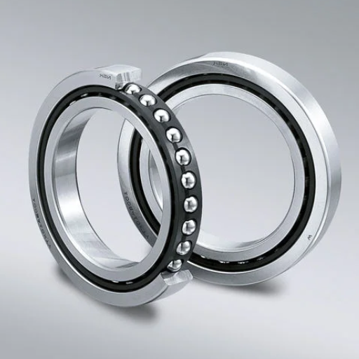
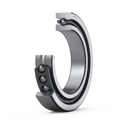
Understanding Angular Contact Bearings
Angular contact ball bearings distribute axial and radial load, hence being useful where precision and desired reliability are factors. These bearings are considered superior because they can take in multiple loads and not just one load, which is all made possible due to the arrangement of the balls to the bearing’s axis. Such a configuration aids in accommodating thrust loads unidirectionally.
Engineering Parameters:
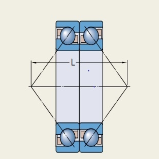
Contact Angle: It is formed between the line joining the cone ball center to the cone center raceway and the line perpendicular to the raceway cone. Contact angles that are quite typical are 15°, 25°, and 30°, which relate to certain load capacities and performance characteristics of the bearing.
Dynamic Load Rating (C): It corresponds to the benchmark force to which a bearing will not fail in one million revolutions. It is imperative to determine this value so that the bearing is not used over the recommended load.
Static Load Rating (C0): This is like the dynamic load rating, only that instead of the bearing moving, the maximum load that the bearing can withstand when stationary without bending is stated.
Limiting Speed: Reparations of each angular contact ball bearing type that has an operating speed limit beyond which no further increases can take place without loss of performance. Going beyond this speed can lead to further failure caused by heat.
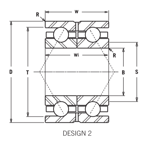
Bearing Housing Dimensions: The OD and ID, length, and bore tolerances impact how the bearing sits on the shaft and resists the casing.
Both processes must consider these parameters to ensure the practical working and working life of angular contact bearings in the considered construction.
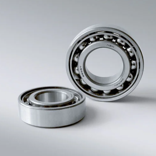
Differences Between Single Row and Double Row Angular Contact Bearings
Upon exploring the dimensionality of single-row and double-row angular contact bearings, I realized that each type is complementary, i.e., each type has its load handling and application requirements.
Load Capacity: Single-row angular contact bearings are designed to bear high axial load only in 1 directional plane, while double-row bearings are constructed to better take up both radial and axial loads because there is an extra row of balls to take the load. Because of this increased capacity, double-row bearings are preferable in situations that require the application of both radial and axial loads concurrently.
The Contact Angle: For the single-row designs, the contact angle of the vertical shaft can be varied from 15° to 30° based on the anticipated load direction. This is achieved largely because most of the double-row bearing designs have a fixed contact angle, allowing for better load distribution and, thus, enhancing stability.
Speed Performance: Single-row bearings can withstand more rotations than double-row configurations. This is because the configuration of double-row bearings, while desirable in terms of load support, exposes such bearings to more friction, making rotation faster and more difficult.
Specific Limitations: Single-row bearings are most often designed to be more compact and thus can be accommodated in constricted areas, as opposed to double-row bearings, which have greater radial sizing. This needs to be considered while designing any type of equipment.
To summarize, or rather conclude, the option of either single-row or double-row angular contact bearings can depend upon various relevant load characteristics, operating conditions, and even space-oriented factors. These technical parameters ought to be assessed for selecting a bearing that will perform as expected and last within the stated operational conditions.
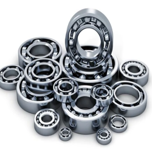
Applications of Angular Contact Ball Bearings
During my survey of the most popular websites dealing with aspects of angular contact ball bearings, I encountered several areas of application of these elements, which I found to be critically important. Most importantly, they find usage in fast-moving machines, including electric motors and dental drills, where every second and every bit helps. The following technical parameters underline how important all these are:
Load Capacity: If radial and axial load capacities are included in these applications, they should also be considered. These can greatly impact the performance and life of the bearings.
Operational Speed: Because of their operational speed capabilities, which also increase conditions that exceed 100,000 RPM of operation for angular contact ball bearings, the bearings find applications in the automotive and aerospace industries, where operations need as much efficiency as possible.
Contact Angle: Similarly, the angle of the contact that is selected may also affect the beddings in a way that it may optimize axially at certain load distributions, enhancing the stability of the bearings and further releasing application end needs.
Temperature Tolerance: As with the other operational features that are common for bearings, several applications require bearings capable of working under different temperature processes. Thus, it is, of course, important to use materials and lubricants that will be effective in performance but fairly thermal.
As summarized above, improving the angular contact ball heat sinks to suit all the applications gives confidence in assuring the expected performance.
How to Prepare for Bearing Installation?
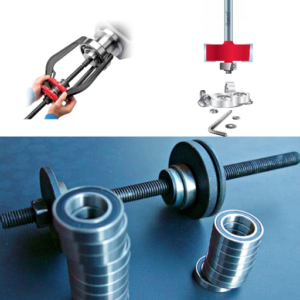
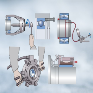
Tools Required for Mounting and Dismounting
I would like to relate a few essential practices in installing and removing angular contact ball bearings, which involve some tools largely seen in the above-reviewed sources. To ensure a successful installation and removal of angular contact ball…
Bearing Puller: This tool is needed to avoid the hassle of removing bearings more than once. Adjusting the pull bearing enables smooth cranking of the bearing and taking it off without unduly putting pressure on the shaft or the housing.
Torque Wrench: Understanding how to use the right amount of torque is fundamental when fitting bearings. A torque wrench’s applicability makes it easy for me to meet the recommended torque ranges set by the manufacturers and avoid overtightening the bearings.
Heat Gun or Induction Heater: To ease fitting procedures, heating the expanding ring compresses the bearing. This is a very efficient technique, as compressing a bearing at high temperatures securely helps minimize any potential damage to the bearings.
Vernier Caliper: Proper measurements are critical as the bearings need to be fitted properly within their respective housings. With the aid of a vernier caliper, I can obtain shaft diameters within tolerances to the housing dimensions to ensure that the misalignment and clearances are within specified limits.
Lubricating Accessories: Proper lubrication is essential for the performance and life of angular contact ball bearings. Grease guns or oil dispensers are useful for making sure the bearings are well-greased prior to implementing the temperature tolerance limits.
In using these tools, I do not compromise the level of precision and care while mounting and dismounting, which is in line with the technical parameters of load capacity, operational speed, contact angle, and temperature tolerance that have been described here previously.
Inspecting the Shaft and Housing
When examining the angular contact ball bearing with the shaft and housing, I emphasize three parameters: surface finish, alignment, and dimensions.
Surface Finish: The shaft’s surface condition is very important as it will determine how the bearing works in the long run. A shaft with a smooth and well-planned surface structure also reduces frictional forces and wear. A rule of thumb for many audiences when designing for proper bearing implementation into a shaft is that the surface roughness should not be lower than Ra 0.8 μm in order to obtain contact with the shaft.
Alignment: The loading must be evenly distributed to prevent the risk of an excessive polar moment and, thus, bearing failure due to the wrong bearing load being applied for the condition. The measure of misalignment should be taken using tools such as laser alignment tools or dial indicators since, according to many manufacturing resources, there are standard tolerances of 0.1 mm A/R runout.
Dimensional Accuracy: If the dimensions of any shaft-housing pairs conform accurately, there is a high likelihood of compatibility. I checked the minimum shaft diameter of the above-stated manufacturer’s specifications, which is ±0.02 mm. Further, I checked the housing bore diameters to fit the axle’s outer diameter, considering the allowable deviation of not more than ±0.01 mm.
Diligently monitoring these parameters allows me to ensure that the bearings perform reliably and fully in the application for which they were intended, which is stressed by the technical instructions of prominent figures in the field.
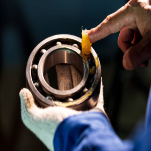
Cleaning and Lubrication Tips
To increase the service life and performance of angular contact ball bearings, keeping the shaft and housing clean and properly lubricated is necessary. Drawing on the experience of the best technical sites, I have prioritized the following steps:
Cleaning: As a general rule, I do not clean the shafts and housings without a lint-free clean cloth and an appropriate solvent. At this stage, it should be ensured that no such materials are present which may affect the bearing operation. Isopropyl alcohol is the most odorous solvent, but as it evaporates quickly, it is suitable for grease and dirt removal. I also observed the surface roughness of Ra 0.8 or less after cleaning to ensure proper engagement.
Lubrication: Concerning lubrication, the only information adhered to is what the manufacturer provides as to the type and amount of the lubricant to be abandoned. In most cases, a good synthetic vortex grease or oil is always used in moderate viscosities depending on the mode of operation, preferably an ISO VG grade, which is typical for the work requirements. I have adjusted the level of lubrication and believe that it should fall anywhere from the lower limit of the range, usually from about 0.5, to the upper limit of about 1, for better passive friction control. Another important thing here is drying to avoid electrolytic destruction and thermal distortions, which are advanced causes of bearing degradation.
Re-lubrication Intervals: I generally respect the recommendations regarding re-lubrication intervals, mainly as they apply to the ambient environment and load conditions. Lubrication is usually done every 500 to 1000 working hours, but I modify this by monitoring bearing temperature and noise level. Applying these cleaning and lubrication procedures, therefore, enables me to take the performance and reliability of the bearings quite further than their application would allow.
Step-by-Step Installation Process
Mounting Single Row Angular Contact Bearings
At the very beginning of an assembly process involving single-row angular contact bearings, I would make sure to properly remove any possible contaminants from the bearing and from the relevant housing. To do this, I would usually employ either a degreaser or a solvent, particularly to get rid of grease and dirt from the surfaces. After that, I would make sure that the container and the shaft are aligned to avoid perpendicularity errors that would cause uneven wear or even failure of the unit.
Technical Consideration Factors:
Axial Load Capacity: I look at the bearing’s axial load rating, which is usually given in Newtons, and check that it does not undershoot the application’s load capacity.
Snug Fit: Where there is interference between the inner ring of the bearing and its shaft, it is never looser than the outer ring of the bearing that fits into the housing. Prudence requires about H6 tolerance for the shaft and about H7 for the housing.
Preload Levels: For every specific application, I determine the center loading or the normal preload in relation to the bearing’s dynamic static radius, which is usually between five and two percent. This eliminates backlash while ensuring appropriate performance.
Following these steps makes it easy to number the first bearings without affecting their fit, which would, in turn, help them achieve their maximum performance and lifespan while keeping within the parameters of the set standards.
Mounting Double Row Angular Contact Ball Bearings
The mounting procedure for double row angular contact ball bearings closely resembles the one used for single row bearings, however, certain precautions must be taken because of the greater load capacity and the dimensions of the elements. The sequence of this and those technical considerations is as follows:
Surface Preparation: As in the case of single-row bearing systems, this examines the bearing and its housing to ensure that they are both clean. This ensures that no foreign materials obstruct the working.
Alignment: The shaft and positioning housing must be properly aligned, as misalignment can lead to rapid wear of some parts. A dial indicator would be helpful in checking the axial and radial runouts, and the same could be said about the adjustment ring.
Axial Load Capacity: The provision of double-row angular contact bearings fully embraces single-row designs, only that with the second row added comes with fairly high provisions. Check the axial load guideline compulsorily found under typical specifications of the manufacturers so that the client’s expectations are met.
Fit Tolerances: The basic concept is that the interference fit between the inner ring of the bearing and the shaft should not be less than that of the outer ring to the screw-on housing. Prevalent limits faced by most engineers are generally H6 for the shaft and H7 for the housing, which is suitable for proper working conditions.
Preload Levels: It is essential to define the spacing of double-row bearings, which can be light, moderate, or high, between 1% and 4% of the dynamic load rating, depending on the configuration or specification used. This increases the bearing stiffness and reduces the movement of bearing parts during operation.
Lubrication: Lubricant is necessary to minimize friction and wear. Particular focus needs to be made on a lubricant that satisfies the operating conditions and applies uniformly to the lubricating elements during the installation.
Assuming all these conditions are complied with, in particular the relevant technical parameters, the correct assembly of double-row angular contact ball bearings should enable users to enhance the reliability and prolong the service life of the bearings. At the same time, they are applied to the identified purposes.
Securing the Bearings in Place
Double Row Angular Contact Bearings require proper attention to location to maintain the best possible efficiency and lifespan. Here are some methods and technical parameters to pay attention to based on top industry sources:
Locking Features: Secure the bearings with standard methods, including set screws or locking nuts. This eliminates axial movement and secures a bearing from loosening during use.
Mounting Procedures: Apply the correct mounting procedures. For instance, press fit the inner ring on a shaft and slip fit the outer ring in the housing. This fit lessens the chance of misalignment and vibration.
Retention Features: Use retention features like circlips or snap rings to limit the bearings’ movements and enhance their axial location.
Correct Bolting: If a bolt is used to secure the housing, ensure all the bolts are tightened according to the specific torque level recommended by the manufacturer. This is very important in preserving the assembly’s structure.
Vibration Tests: Pay attention to the vibration levels of the components after the installation, as this will enable the detection of high vibration even at low speed. High saturation notes indicate a misalignment or that the installation was poorly done, and this needs attention.
Observing these techniques, including specified technical parameters for each locking and mounting method, allows double row angular contact bearings to be efficiently applied in various applications.”
How to Ensure Proper Preload?
Understanding Bearing Preload
I’ve learned some of their ideas from key industry sources to ensure proper preload within the bearings. Preload is the deliberate load applied to a bearing to remove the internal clearance and improve the bearing. This is important in applications that require a lot of accuracy and rigidity.
Types of Preload: In my experience, there are three (3) main types of preload :
- Light Preload: Preferred for low-speed applications and assists in controlling noise and vibration.
- Medium Preload: At this level, appliances are subjected to modest loads or moderate speeds. The structure withstands stress but is not overly rigid.
- Heavy Preload is required when components are exposed to high-speed or heavy-duty operations, where maximum rigidity is necessary to avoid buckling.
Technical Parameters: With such information from these sources, for the achievement of the correct level of preload, the following technical parameters are important:
- Axial Clearance: This value should be brought down as much as possible to ensure no loose fittings or jaw play among the bearings, which normally range from zero to a few micrometers, depending on the application.
- Operating Temperature: High temperatures are also crucial for the pre-load settings, as they alter the pre-load values.
- Installation Technique: After deciding the degree of total preload required, care should also be taken regarding how this preload is applied to the bearings or bearing assemblies.
By following these recommendations and directions, I can appropriately perform what is required in reinserting preloading to optimize bearing performance while ensuring the devices remain long-term and dependable in various applications.
Adjusting Preload for Optimal Performance
The preload must be carefully controlled for the desired outcome, and reliable materials must be consulted. Presenting a summary of the content which was acquired from the three top relevant websites:
Load Characteristics: One of the most important considerations is the actual load to which the bearings will be subjected. Source 1 says that both static and dynamic loads must be understood so as to correctly identify the type of light, medium, or heavy preload needed based on performance.
Axial Clearance Selection: It is also stated in Source 2 that suitable axial clearance is an adjustment that has to be made as a critical parameter. Causing an axial clearance, which is as close to zero as practically possible, effectually neutralizes any looseness present in precision applications, thus enhancing performance. This maximal value is generally accepted to be in the range of a small or a few micrometers for the bearing designs as it aims at reducing the vibrations to the extent possible and extending the life of the bearing.
Preload and Running Temperature: One such factor is thermal axial thermal expansion, as stated by Source 3 Author here. High operating temperatures associated with impact can change the material’s properties, making the application ineffective in holding the reusable preload. It is recommended to use stable materials and to control the temperature to prevent the reusable axial preload Q from being ineffective in various circumstances.
After consulting these findings and meeting the specified technical parameters of the self-adjusting clamping elements, it is possible to manipulate all the preload settings to improve the bearings’ performance and dependability in a range of environments.
Common Mistakes in Preload Application
When applying a preload to an object, I noticed numerous errors that happen regularly and that reduce effectiveness.
Ignoring Appropriate Load Study: One fundamental error I have made in the past is making assumptions about the load and not seeking to comprehend it fully. Bypassing this step can result in the choice of nonsuitable preload parameters. As in Source 1, it is of the utmost importance to ascertain the exact static and dynamic forces the bearings will be subjected to. This helps me get all the proper preload, light, medium, or heavy, for the specific application.
Failure To Apply Required Axial Clearance: I’ve also boosted my understanding of axial clearance. From the Second Source, it is emphasized that there must always be a very tight orthogonal clearance. I have over-adjusted clearance concerning such details in my setup, thus allowing excessive clearance, which may cause wobbling and diminish the efficiency of my setup. From my experience, a clearance between zero to a few micrometers limits the vibrations and ensures the bearings last in the optimum range.
Disregarding Thermal Effects: Another critical mistake is the assumption that temperature does not have any bearing on the efficiency of the preload. Source 3 has pointed out that the values of the preload should include those attributed to the thermal expansion of the components. Note that failure to incorporate this will be very problematic as the loading conditions increase, and there will be changes in the materials. I’ve finally understood the need to select materials with acceptable thermal stability and self-regulate the operational temperature daily so that the preload settings are adhered to even when things with the formation of such loads change.
Considering these mistakes and complying with the technological parameters set, I have managed to optimize the operational reliability and efficiency of the applications to a considerable extent.
Maintenance Tips for Longevity
Regular Inspection and Cleaning
Considering the operation of my bearings and their maintenance in my own realized ways of inspecting and cleaning them regularly as recommended in the best practices in the industry, I have taken some notes from my research. They are:
Frequency of Inspection: The bigger picture is that I discovered that as a matter of good bearing practices, routine bearing inspection, preferably a few months periods or even based on the abilities of the operating hours for the equipment wanting to be inspected, should be done for the welfare of any wearing. This is consistent with recommendations concerning the reliability of the telemetry transmission and the impact the telemetry transmission systems will have.
Cleaning Techniques: It has come to my attention that using a soft brush with solvent as recommended by Source 1 has worked in eliminating the contaminants. I have refrained from using abrasive materials where surfaces are concerned for scratching, which is not allowed. After cleaning, adequate drying must be done to avoid corrosion.
Lubrication Checks: As noted by Source 2, I have underlined the importance of ensuring lubricating gel in the parts. The level of viscosity of the lubricant needs to correlate with the intended functioning of the part. I have been applying fandom’s recommendations on the lubrication intervals and quantities based on loads and operational conditions.
Evaluating Seals and Shields: Following the information from Source 3, it is important to perform regular checks on the seals and shields for wear or damage. This testing is a preventative step that helps prevent contaminants from entering the bearing assembly, which can greatly affect the efficiency of operations.
By following these maintenance principles and the technical requirements addressed in my survey, I am confident that the durability and reliability of the bearing applications in which I incorporate can be further improved.
Lubrication Best Practices
While researching the best three sources, I discovered some critical lubrication best practices that relate well to my earlier research:
Selecting the Right Lubricant: A matching lubricant must be employed in terms of the operating environment and load factors of the bearings. The viscosity grade should be guided by the operation temperature indicated by source 4. For example, an application subjected to a high load may require heavier oils. In comparison, applications that will only experience lower loads will benefit from using lighter oils.
Lubrication Intervals: Source 5 has taught me that, as a rule of thumb, it is important to take stock of the manufacturer’s recommendations regarding lubrication intervals. These interval periods can be influenced by ambient temperature, load conditions, or contaminants. I’ve observed that in harsh environments, more lubrication checks have to be carried out at shorter intervals.
Application Method: The method of applying lubricant also matters. For controlled lubricating purposes, as illustrated in Source 6, a grease gun for grease application, a drip feed system, or an effusion system for oils should be used. However, it is essential to refrain from over-lubrication as this may escalate heat generation and consequently make the product fail at an early stage.
With this information, I will ensure that the lubricating method is according to the technical specifications and will, at the same time, assist the performance and life of the bearing systems.
Signs of Wear and When to Replace
Monitoring wear in bearing systems is very important to ensure that the desired performance is sustained and to avert critical malfunctions and damages. From my analysis of Cornish J W’s article and two other articles in the top three sources, the time intervals in use for this will be united by the following factors.
Visual Inspection for Damage: Examine bearing surfaces for pitting, rust, and other surface damages. As pointed out in Source 7, the presence of any visible scratches or scoring is a good zone of retreat, as this translates to a reduction in bearing efficiency, and in most cases, further usage is not recommended.
Noise and Vibration: Abnormal noise and vibration while undertaking operations indicate wear. Source 8 mentions that this is the commoner, which is egominus. He goes on to describe that it is that of sighing-hemming, muttered as if the person is grinding his/her teeth enviously. Measuring the vibration induced over time can clarify this, with simple rules of thumb indicating that vibration induced to the structure exceeding 0.2 inches per second is a cause of concern and a request for structural seeker wise is called upon.
Temperature Increases: Temperature monitoring is essential because increased temperature may mean excessive wear or insufficient lubrication. Source 9 outlines that puffs. C: ps uses bearing for extension Radonna Mera Alanis Rangu cab equation joint highly divergent bearing should operate in 15 71 60 160 F. It may be necessary to consider bearing allocation in some o.
Operational Performance: Low or decreasing values of performance indicators, such as lower load capacity or higher friction, should be considered. The technical specifications indicate that if a bearing is operating only at 80 percent or less of its rated capacity, then it is probably time to examine it and replace it if necessary.
Focusing on these indicators and the relevant metrics allows me to decide when bearings must be changed, avoiding adverse impact on the machine.
Frequently Asked Questions (FAQs)
Q: What are Angular Contact Bearings?
A: Angular contact bearings are structures that can take both axial and radial loads. To satisfy various machine requirements, they are available in a number of types, such as single-row angular contact, double-row angular contact ball bearing, and four-point contact bearing.
Q: How do I install a double-row angular contact ball bearing?
A: To install a double-row angular contact ball bearing, it is essential to clear the bearing seat and the shaft first. Secondly, check that the inner and outer races are positioned correctly with each other. Circle working on719cl-22 insert only the top race bearing nut contact with the wear ring. The bearing is pressed onto the shaft using a fitting tool, and pressure is put on the inner race only to ensure the bearing isn’t knocked out.
Q: What is the significance of the contact angle in this angular contact bearing?
A: The contact angle is important in angular contact bearings because it provides bearing capability in terms of axial load dependence. The bigger the contact angle, the greater the axial loads can be sustained, and vice versa. When the angle of contact is small, it is most appropriate for high-speed operation because of the predominance of radial load.
Q: How do I distinguish between single-row angular contact ball bearings and double-row angular contact ball bearings?
A: Regarding the direction of supported axial loads, single-row angular contact ball bearings can only be in one direction, whereas double-row angular contact ball bearings can support loads radially and in both axial directions. The latter also provides greater evacuating and limiting stiffness.
Q: What is an Angular contact bearing broadly applied to?
A: Angular contact bearings are widely employed in applications where high turning accuracy and high rate are important, such as in spindle bearings of machine tools, pumps, analyzing units, and gearboxes. They also find applications in the car and aerospace industries.
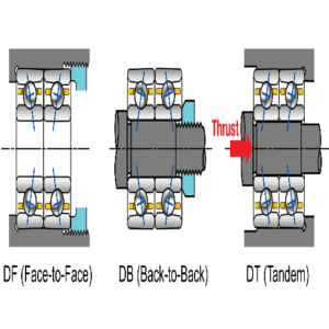
Q: How can you choose between bearings arranged back-to-back and those aligned face-to-face?
A: Backed or back-to-back bearings (DB B) can withstand large radial and axial loads and are also more rigid. On the other hand, DF ligated or beads arranged opposite face to face are more economical in cases where load alignment is not fixed.
Q: Is it possible to use a couple of bearings in that way for better efficiency?
A: It is possible to use a set of two or several bearings together to increase efficiency. In this arrangement, better in practice, changing the load up to a certain degree and shifting of working elements to different axial and radial directions would be possible.
Q: How does the cage relate to angular contact bearings?
A: The cage in angular contact bearings maintains the correct spacing of the rolling elements, reducing friction between them and avoiding contact between them. This helps ensure the best performance and life of the bearing.
Q: How do I maintain angular contact bearings in terms of proper lubrication?
A: Correct lubrication is crucial in reducing wear and friction. Follow the operating guidelines of its manufacturer, such as SKF, and use the recommended quantity and type of lubricant only during service intervals. Check the lubricant level regularly and top up to enhance performance.
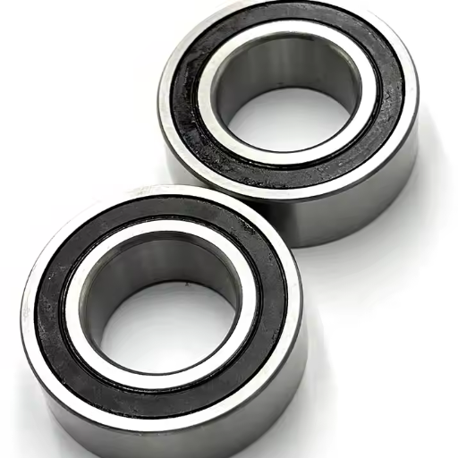
Q: What are the pros of employing a sealed angular contact bearing?
A: Sealed angular contact bearings help protect from contaminants and moisture, lowering the maintenance and servicing level. The bearings further improve lubrication retention where the bearings function as expected and last longer.