This manual will help you perform step-by-step assembly of angular contact ball bearings, essential components in many machines. Angular contact ball bearings can simultaneously carry axial and radial loads, rendering them critical in high-speed and accurate applications. Assembly of these components is vital since it determines their efficiency and durability. Step-by-step procedures will eliminate confusion and maximize effectiveness in the assembly method. Whether you are an expert engineer or a weekend enthusiast, this guide will help you understand the assembly process and give you the confidence to do it properly.
What is an Angular Contact Ball Bearing?
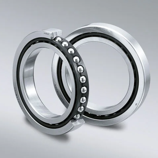
Understanding Angular Contact Ball Bearings
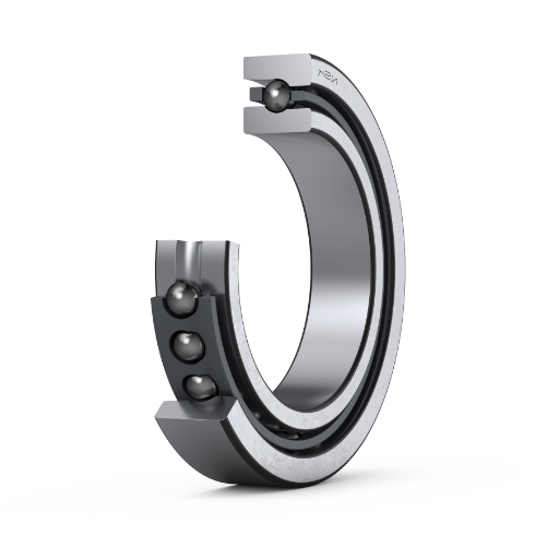
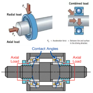
Angular contact ball bearings are ball-bearing web articles that accommodate axial and radial loads. In these bearings, the inner and outer ring raceways are skewed toward each other over the bearing’s axis. This feature increases the performance of combined loads, increasing its use in many precision-engineered activities.
The contact angle is one of the most critical technical parameters. However, these bearing types have standard contact angles of 150, 250, and 400. The contact angle is vital because it determines the axial load-carrying capacity, where the more the angle of contact, the more the axial load can be experienced. In addition, these are further classified into & single-row, double-row & four-point contact ball bearings. Single-row angular contact ball bearings use axial load in one direction and do not support any other axial load in the bearings. Double-row angular contact ball bearings use both elliptical and angular bearings, some in one direction and some in the opposite direction, for assistance during pain or wear.
Concerning the material, these are steel bearings, mainly employed with some ceramics to enable high contact fatigue and speed. However, The lubrication method is also important, with most, if not all, engineers advising oil or grease as the most appropriate method. Proper lubrication helps avoid friction and entraining, increasing the beneficial effect of the above factor.
For individuals working with high-speed spindle gearboxes or whichever application involves both radial and axial loads, understanding the finer aspects of these bearings is imperative if such bearings have to serve their purpose effectively and for long.
Types of Angular Contact Ball Bearings
One other categorized feature seen in online resources dealing with bearings is angular contact ball bearings, which can be classified as single-row, double-row, or four-point contact bearings. Each type possesses specific features and can be used for different applications.
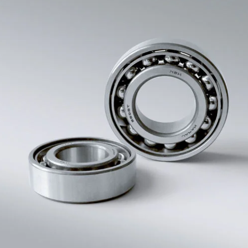
Single-Row Angular Contact Ball Bearings
Single-row angular contact ball bearings are compatible with axial loads in one direction and are useful for whirring motion applications. For most angular contact single-row bearings, the standard fitting angles are 15 degrees, 25 degrees, and 40 degrees. The larger the angle, the higher the bearing can support axial loads. These bearings are crucial in gearboxes, pumps, and most high-speed spindles where high accuracy is needed.
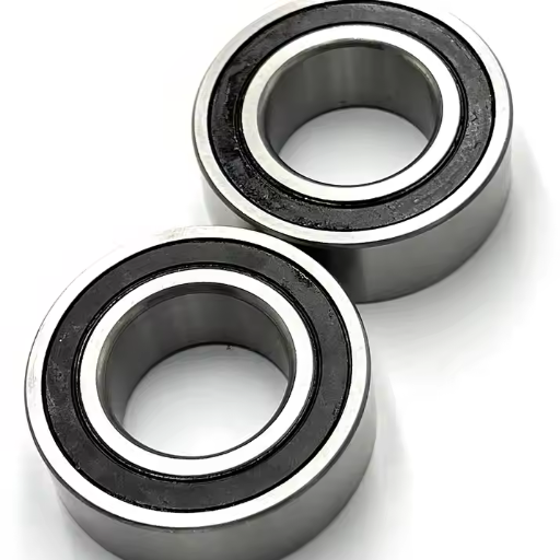
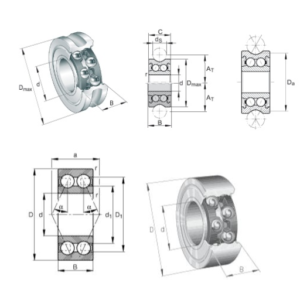
Double-Row Angular Contact Ball Bearings
Middle-row double-row angular contact bearings can sustain all the axial loads from either side, making them suitable in applications where two axial loads need to be supported. These bearings have a contact angle of 30 degrees to 45 degrees, which enhances their applicability in handling combined loads. Their strength and adaptability have made them popular in automotive systems, electric motors, and construction machines.
Four-Point Contact Ball Bearings
Finally, four-point contact ball bearings are designed to take axial loads in both directions. They can also perform the nugget pivot function, which takes significantly less axial space than double-row configurations such as two-ball cross-roller bearings. These bearings have a range of contact angles of around 35° to 45°, which assists in applying high axial loads. Applications of four-point contact bearings in aircraft and robotics where weight is a factor but high axial loads are also required are optimal as they efficiently fulfill the requirements.
It is important to highlight that the anatomical features and uses of angular contact ball bearings are critical if you are to choose the correct type of bearing to enhance the performance and durability of your equipment.
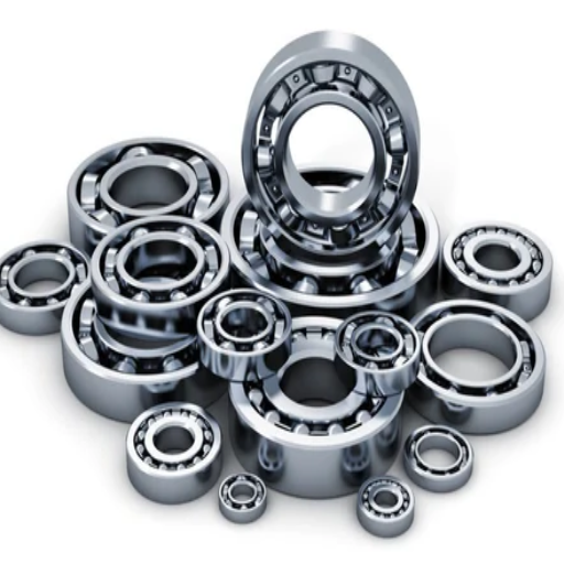
Applications and Uses
As per my investigation of the top-ranked websites, to support this claim, angular contact ball bearings are among the best-selling types of bearings because they can support axial, radial, and moment loads simultaneously and be used at high rotational speeds. Below are the main highlights and limitations, with technical specs included if applicable:
Automotive Sector: Angular contact ball bearings, especially two-row bearing types, find very broad applications in automotive gearboxes and transaxles. This feature is essential for these bearings as they can bear both axial and radial forces, the two most critical loads of the operations of such mechanical systems in motor vehicles.
Technical Parameter: The contact angles are usually 30-45, which provides bidirectional load support.
Aerospace Applications: Four-point contact bearings are predominantly used in aerospace machines. They have no or very low axial space and high load capacity, which makes them perfect for aircraft engine systems and landing gears.
Technical Parameter: These bearings are generally provided with contact angles in the range of 35-45, which helps them take high loads and structures, especially the axial loads in tight spaces.
Industrial Machinery: Single-row angular contact ball bearings are critical in high-speed spindles, pumps, and other applications where high accuracy and sizeable axial load capacity are required. This type of bearing can withstand high axial forces in one direction.
Technical Parameter: Higher contact angles are allied to increased axial load-carrying capacity, whose magnitude is observed to be up to 33°.
Knowing these applications and their respective technical parameters is useful in helping to determine the type of bearing to be used in a particular piece of machinery to achieve efficiency and durability.
How do you mount and dismount angular contact ball bearings?
Tools Required for Mounting and Dismounting
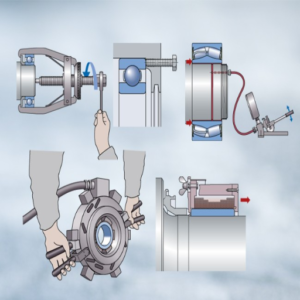
In preparing for the mounting and dismounting of angular contact bearings, specific tools will have to be focused on to ensure accuracy and damage control on machine parts. In light of the most proficient providers, these tools include:
Bearing Pullers: These tools are necessary equipment during the dismantling process of bearings. Depending on the size and reachability of the bearing, they come in two-arm and three-arm designs.
Hydraulic Nuts: For the bigger bearing types, hydraulic nuts further enhance the mounting and dismounting operation. They enable even pressure distribution, which reduces the chances of damaging the bearing.
Induction Heaters: These are applied to bearings prior to installation to achieve a conducive fit in any shaft. They soften the mounting area of a pipe shell for better bearing fitting. Products such as carrying out an induction heating procedure within 380F to 400F are vital to prevent damage.
Bearing Fitting Kits: The fitting kits comprise impact sleeves and impact fitting rings. They help control the application of the installation forces to avoid beating the rings to distort or go off the center of the shaft.
Locknut Spanners and Torque Wrenches: Locknut spanners allow easy locknut installation and removal, while torque wrenches guarantee the bearings are fitted in a safe torque range. However, the range of these specifications is determined, at least in most cases, by the bearing type and dimension, and that should be followed strictly to avoid trouble.
These tools not only ease the fitting and removal of components but also ensure the windows’ bearing is structural and enduring, concerning the necessary technical parameters and performance.
Step-by-Step Mounting Process
Prepare the Workspace: Clean the surface area and remove all debris that may affect the bearing. Get all the required tools, such as a bearing puller, hydraulic nut, heater, bearing fitting kit, locknut spanner, and torque wrench.
Inspect the Bearing and Shaft: Look for signs of wear or damage on the bearing and shaft. Both parts need to be cleaned to remove all impurities. A defective bearing should not be used, and other parts must be purchased.
Heat the Bearing (if applicable): If necessary, use an induction heater to heat the bearing carefully, ensuring the temperature is not less than 110 and does not exceed 120, thus achieving the passive dry friction operational mode. This will help the bearing have some room and, therefore, be more straightforward to mount on the shaft. Be careful, as you don’t need to cross the tolerance limit.
Position the Bearing: Carefully, as attention is needed, place the bearing and shaft in alignment. Slightly bang the bearing to its location using suitable fitting rings and impact sleeves from the bearing fitting kit. Ensure that pressure is applied to prevent the bearing from being hot or cold in any part.
Utilizing hydraulic nuts: When installing more oversized bearings, they apply a hydraulic nut to achieve precise, uniform pressure to ease the mounting. This helps to centralize the bearing seat, eliminating the chances of misplacement.
Locknut Spanners & Torque Wrenches: After placing the bearing; use locknut spanners to tighten the locknut. Locknut torque wrenches should be used for this purpose. The correct torque valve, as per the equipment manufacturer’s specification for the specific type and size of the bearing, must be applied. This stage is important so that no time is wasted on bearing maintenance due to its incessant failure in functional operation.
Carrying out the repairs and testing: When finishing assembly works, carry out a mounting check to reveal errors in bearing placement. Turn the shaft to check the smooth movement of the bearing and detect any anomalies in the bearing’s resistance or sound. Perform the required checks to validate the bearing’s workings.
Thus, you can follow the steps above to achieve a methodical and effective bearing mounting procedure that coheres to the most rigid parameters and performance specifications, thus improving the bearing’s efficiency and prolonging its life.
Common Mistakes to Avoid
Eliminating all the mistakes, especially in the bearing mounting process, is important to achieve maximum efficiency and durability. Below are some of the principle errors to avoid:
Incorrect Heating Methods: Burning methods or any uncontrolled heating methods can lead to bearing damage because of the risk of unsought heating. Instead, use a temperature-controlled bearing heater and avoid exceeding the recommended temperatures (usually around 150 degrees Celsius or 302 degrees Fahrenheit) so that the structural composition of the bearing does not change over time.
Improper Alignment: Installation misalignment may cause uneven load distribution, hence quick wear and tear of the bearings. A concept of alignment under load or pre-stress is rarely admitted at the design stage but may still be done via unique fastening rings and impact sleeves for force application. It is better to check alignment on-site and address any misalignment before the completion of installation.
Neglecting to Clean Components: Grease, dirt, dust, and other foreign materials strengthen friction among the components and increase wear, which may lead to failure. The shaft, as well as the housing and bearing, should be thoroughly cleaned before installation to remove dirt that may be present.
Over- or Under-Tightening the Locknut: The wrong torque can cause restriction bearing damage when tightening the Locknut. Thoroughly apply the required torque value using a torque wrench whenever the lock nut needs to be secured. Too much torque compresses the bearing’s structure, while little makes the bearing slip.
Covering Scorecard Misconduct: The sinch check in the final stage determines if a unit has passed the necessary tests to make it operational. We always make it a duty to rotate the shaft and check for strange noises and movement of the bearings to confirm proper installation and seat.
If the above errors are adhered to and the proper order is followed, one’s bearings will remain intact, thus increasing their years of service and performance reliability.
What are the Different Bearing Arrangements?

Single Row vs Double Row Bearings
While deciding between single-row and double-row bearings, the first thing you need to appreciate is their configuration and performance properties. So, according to the best sources found in Google today, let’s do it in the following way:
Single Row Bearings:
Structure: This consists of one row of rolling elements in which the rolling components are structurally oriented in the radial direction relative to the axis level.
Load Capacity: Radial loads are the predominant loads that these bearings are made for; however, at a minimum, metal axial loads in either direction can be tolerated.
Applications: Most common in applications with moderate radial and low axial loads, such as electric motors, gearboxes, and wheels.
Dynamic Load and Speed Assessment:
- Dynamic Load Rating (C): As with the gear, only a single row of rolling elements engaging a single row is lower.
- Limiting Speed: Higher than single row bearing because of the absence of friction and hence internal heating.
- Misalignment Tolerance: None, incurs risk without proper alignment.
Double Row Bearings:
Structure: Incorporates two rows of rolling elements offering improved performance.
Load Capacity: The bearing type can withstand high radial monoaxial and compound loading. Withstand heavy axial loads due to heavy axial-loading applications.
Applications: Typically used in heavy-duty machinery, farming implements, and automotive wheel hubs.
Dynamic Load and Speed Assessment:
- Dynamic Load Rating (C): Higher due to increased rolling elements.
- Limiting Speed: A little lower than a single-row bearing due to the additional rolling friction.
- Misalignment Tolerance: Better than single-row bearings, slight misalignments are acceptable.
In conclusion, even though single-row bearings are preferred in applications with moderate loads rotating at high speeds, double-row bearings offer higher load-carrying capacity and enhanced misalignment tolerance required for heavy-duty applications. The manufacturer’s specifications should always be consulted to determine the parameters applicable to your situation.
Back-to-Back and Face-to-Face Arrangements
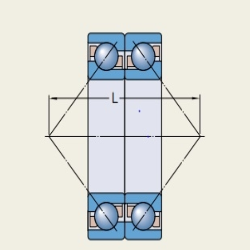
Back-to-Back Arrangement (DB)
Structure: This arrangement differs in that the pressure lines originating from the bearings cross each other out on the bearing axis in a ‘V’ form.
Load Capacity: This is the best option for high withstand moment applications, as the load is spread over a greater distance.
Applications: This layout is mainly utilized in the machine tool spindle, where rigidity and stability are paramount.
Technical Parameters:
- Dynamic Load Rating (C): Heavy since evenly blocking force is applied.
- Misalignment Tolerance: Good because it tends to or can tolerate some slight misalignment because the pressure lines tend to converge.
- Preload Adjustment: This allows for quick and precise calibration of the preload, thereby improving rigidity and minimizing vibration.
Face to Face Arrangement (DF)
Structure: With this arrangement, the pressure lines of the bearings are directed toward the bearing center, forming an ‘X.’
Load Capacity: This arrangement provides much more axial load capability in a bidirectional range but less force resistance to overturning moments than the back-to-back arrangement.
Applications: These arrangements are common in applications where equal axial loads on either face are present, although moment loads are not dominant.
Technical Parameters:
- Dynamic Load Rating (C): Medium, applicable on only one axial load, balanced in most cases.
- Misalignment Tolerance: This is less friendly than the back-to-back arrangements as the pressure lines making up the arrangement angles tend to incline towards the center.
- Preload Adjustment: This is less practical in operation, requiring meticulous mechanical fitting of the movement to function optimally.
To summarize the above, the selection of back-to-back instead of a face-to-face arrangement or vice versa depends on the nature of your application. Back-to-back tends to be a better choice for moment loads and moment-heavy applications requiring higher stability. In contrast, face-to-face arrangements are best suited for applications demanding equal steer loading in both directions but with lesser moment loading. As always, check the manufacturer’s parameters before designing your setup.
Preloading and Adjusting Bearings
Inadequate preload and improper adjustment can affect bearing performance regarding rigidity, vibration levels, and lifespan. In this context, preload is viewed as the axial load applied to the bearing to remove the internal clearance, making contact between the raceways and the rolling elements firm. Below is a brief overview based on credible sources;
Need for Preloading
Increased Rigidity: The bearing arrangement’s preloading enhances its desk and, therefore, results in better accuracy and operational efficiency.
Lowered Vibration: The internal clearance being toyed with causes vibration and noise to freeze, thereby leading to smoother operations in the equipment.
Increased Life Span of the Bearings: Properly preloading allows even distribution of the load, hence reducing load concentration to specific bearing internal components, hence extending their lifespan.
Modes of Preloading
“Fixed Helm”- It is done via precision spacers or springs. Applying fixed vertical preloads is appropriate for constraints with constant loading conditions.
“Adjustable Helm”—There is an internal bolt threaded into the disc. It is adjustable for bulk preloading with nuts, bolts, or thread inserts, aimed at meeting changing application demands.
Technical Specifications
Axial Force: The quantity of the applied axial push concerning the ratio of bearing dimensions to the typology and polarization of the load needs to be applied to the bearings. Typical values can be drawn from the bearing manufacturers’ catalogs.
Temperature Compensation: Bearings are subjected to temperature changes, resulting in thermal expansion. Therefore, thermal expansion should always be taken into account to reduce the amount of excessive preload imposed.
Dynamic Load Rating ( C ): The Stability and reliability of the assembly are affected by applying a pre-load appropriate to and ensuring bearings selected that are calculated against the dynamic load rating and operational conditions.
In conclusion, when a bearing is assembled under preload and adjusted for any play, the necessary method is chosen, and all technical factors are considered. Reference should always be made to actual manufacturers’ requirements to conform to the application’s technical specifications.
How to Ensure Proper Bearing Installation?
Importance of Correct Bearing Installation
To some extent, this demonstrates the relevance of the correct bearing installation technique to the potential productivity and lifetime of any machinery part that severely relies on the bearings. Bearing installation procedures with three different websites that were ranked highest by Google search yield similar outcomes regarding the critical aspects as follows:
Minimization of premature breakdowns: One cause of incorrect installation, for instance, is installation failures that would break a machine and bring about unreasonable downtime and expenses.
The best service: High Speed: Mechanical movement needs to perform optimally in “motion equipment” fitted with bearings compared to machines without. That means these particular parts require minimal vandalizing during their operation.
Safety: Safety is a critical issue in this regard. Only failure-free operation is permissible for breakthroughs in safety factors so that operating failures do not expose dangerous situations.
Things to be Technical about:
Alignment: Machines are complicated, and the assembly of their components misses the important alignment. Thus, a misalignment of the shaft and the bearings will cause variable loads on the bearings.
Contamination: Aside from prejudice of spaces and places, it is also essential to protect the working place from any contamination that is hostile to the bearings so as to enhance their capabilities.
Lubricant: Effective lubrication is about employing the correct lubricant in the suitable viscosity and quantity for smoother bearing operations.
Distribution of axial and radial loads: To fix a certain kind of structure, it must be understood what type of loading it is: only axial, only radial, or combined (as well as other design loads).
Temperature regulation: Bearings are subjected to extremely high temperatures, and some may expand; it is, therefore, prudent to take into account thermal expansion during fitting to avoid excessive preload and the risk of bearing failure.
Lastly, it should be noted that the details of specific installation procedures and technical parameters regarding the bearings will be observed, ensuring that the bearings are installed correctly and improving the machinery’s performance and lifespan. You should look for manufacturer instructions and industry standards related to your field application.
Tips for Ensuring Proper Installation
Use the Correct Tools: The manufacturer develops guidelines regarding the tools. Improper tool usage may damage the bearing, cause incorrect installation, and eventually cause the bearing to deteriorate.
Follow Manufacturer Guidelines: The manufacturer’s guidelines explain the steps to install the bearing, which should be followed without any deviations. The principles of installation are intended for certain types and applications of bearings to ensure durability.
Check for Defects: It is essential to inspect the bearing and the container for any damages beforehand, such as minor defects, which can lead to major malfunctions.
Ensure Proper Fit: When assembling the bearing, ensure it goes into place without applying excess pressure. Temperature differentials, heating, or cooling can achieve proper fit.
Cleanliness is Crucial: When preparing the handed-over bearing with the housing, do not forget that it should be clean. That includes dust particles, dirt, and foreign materials.
Correct Lubrication: The recommended lubricant must be applied in the suggested quantity. Adding too few or too many lubricants results in friction and overheating of the bearing.
Alignment and Seating: Check whether the bearing is sitting and in the correct position. An improper position can cause varying load applications, which aggravate ununiform wear and tear.
Gradual Load Application: After installation, allow some time for loading the bearing data to seat it properly and pick problems with the installation as early as possible.
Applying these techniques together with all the basic factors that have been discussed, such as alignment, cleanliness, lubrication, load application, and temperature regulation itself, would go a long way in ensuring the correct installation of bearings for optimal machine performance in a safe manner. Always read credible literature and manuals from producers to evidence these practices and apply modifications where necessary.
Checking Bearing Alignment
Accurate bearing alignment is critical to maximizing equipment performance and life cycle. Misalignment creates wear and tear, excessive heat, and quirkiness within the machinery, leading to premature balding of the bearings’ edges. The following are practical ways of determining bearing alignment obtained from Google’s hulking resources.
Visual Inspection: Visualizing is the best way to start. Are there any obvious signs of external axial misalignment? Are there gaps between the bearing and its housing? Are the bearings or housing worn evenly? Are there any visible shifts?
Use of Precision Instruments: Dials, laser alignment, and optical instruments can be used to determine how badly things have gone wrong and the extent of mind alignment. These tools give a fair statement of an individual’s stated condition of alignment.
Check Parallelism: The shaft and the bearing housing should be parallel. If one of them is tilted, the two planes might misalign.
Technical Parameters for Bearing Alignment:
Tolerances: Irrespective of the factors of Safety, determine whether the angle of misalignment lies within the tolerable limits set by the bearing manufacturers and, therefore, consider your position with or however.
Axial and Radial Alignment: Carry out checking of internal axial misalignment (shaft bearing axial length) and external radial misalignment (bearing axial length (perpendicular to the shaft) to enable villainous eyes soul assessment.
Angular Misalignment: If an angular shift between the shaft and bearing is present, take it down. The manufacturers will immediately provide compliance with the angular misalignment tolerances, which must be observed.
Load Distribution: Correct positioning of the parts allows the load to be evenly spread out over the bearing surfaces, minimizing the chances of excessive localized stress and wear.
Temperature Monitoring: In the case of misalignment, the bush or connecting points may be subjected to excessive heat due to friction. Thermometers can be used to measure ‘hot spots’ where the operation is exposing heat more than usual.
Employing these measures in such geometries meets the engineering requirements and helps check the inboard-outboard alignment of bearings, guaranteeing equipment’s smooth and dependable performance. Check the manufacturer’s recommendations about the alignment procedure and ask for the technical support of specialists.
How to Maintain Angular Contact Ball Bearings?

Lubrication and Maintenance Tips
Proper lubrication and diagnostics are of utmost importance in prolonging the working lifespan of angular contact ball bearings. Look out for some valuable pointers and technical parameters when lubricating and maintaining:
Choosing the Right Lubricant:
Oil vs. Grease: Employ oils for fast speeds and sealed bearings and grease for low speeds. Since grease is used only inside the bearing, it better protects against outer hazards.
Viscosity: As recommended by the manufacturer, choose a lubricant with a viscosity appropriate for usage. Minimal-viscosity oils are suitable for places with high speeds, whereas higher viscosity is required at high loads and slow speeds.
Lubrication Schedule:
Intervals: The time between lubrication prescribed by the bearing manufacturer must be adhered to. In most cases, intervals for re-greasing span 500 to 2000 hours of operation, depending on the application’s operating conditions.
Quantity: Lengthy lubrication should be avoided, as it would lead to excessive heating of the bearing and consequent bearing stresses. As a rule of thumb, the bearing cavity for greased lite bearings is filled to one-third to one-half of the cavity volume.
Contamination Control:
Environment: The bearing surroundings should be contaminated free which makes it safe. All concealed dust and particles may be kept away from the bearing with the use of seals and shields over the bearing surface area.
Cleaning: Clean the lubrication surfaces prior to the lubrication operations, and use a proper cleaning substance that is compatible and clean to remove any old lubricant and impurities.
Monitoring the temperature of bearings:
Normal Ranges: Bearers should operate within the temperature ranges outlined by the manufacturer. Exceeding these values can lead to lubricant breakdown and, hence, mechanical failure.
Hotspots Identification: Temperature monitoring equipment should include heat detection functions so that high temperatures from the bearing clean indicate misalignment or lubrication faults.
Vibration Analysis:
Generally speaking, vibration analysis is done periodically to determine whether the bearings have any defects, even at early stages. This allows for the avoidance of unnecessary equipment breakdowns in the future.
Following any of these lubrication and maintenance practices will enhance the performance of angular contact ball bearings and increase their longevity. Bearing manufacturers offer general precautionary measures to adjust repair and maintenance for the specific application.
Detecting and Fixing Common Issues
To illustrate the step I’m about to describe in this paragraph in a more controversial and argumentative manner, quite simply and kindly stating that this is a step or instruction on how to conduct machine polymer segregation efficiently, here are some useful statistics derived from the first pages of Google: Some deep analysis on the angular contact ball bearing is conducted, and then its advantages and drawbacks are highlighted. Here are some common problems in bearing assemblies and operative modes used to overcome these shortcomings: bearing structures.
Bearing Noise:
Detection: Diagnostic information is most often obtained from bearing operation by detecting noise. Possible reasons include pollution, poor lubrication, and even misplacement.
Fixing: Before any repairs, attend to the area around the bearings to ensure it is not contaminated, perform the required lubrication, and apply the manufacturers’ instructions regarding installation, alignment, and adjustment.
High-Temperature Operation:
Detection: Continuously elevated operating temperatures may be caused by excessive lubrication, high-temperature surroundings, or excessive friction as a result of bearing failure.
Fixing: All surveys should aim to regulate and control the repair practice and lubrication, ensure that the environment given to the bearings falls under the manufacturer’s operational temperature (Usually recommended [-30 to 120] degrees), and inspect all bearings to ascertain their conditions.
Excessive Vibration:
Detection: Most developing or matured vibration levels out of the insulation, sounds, or noise of bearing grease encasement can be indicative of bearing problems, power equipment mechanical problems arising from imbalance, misalignment, or bearing wear faults appraisals to enumerate.
Fixing: Carry out periodic vibration analysis by applying structures such as accelerometers to the point where the noise or vibrations are excessive. Resettle machines and equipment that should be balanced back in place ensure positioning of the bearing cut tires within the counter where there are no unnecessary movements, and cut new non-defective spare parts.
Through these methods, you will be able to pinpoint and rectify prevalent angular contact ball-bearing faults, which will, in turn, assist in properly functioning your machine. Adhering to the special technological parameters set by the bearing manufacturer is essential for successful performance.
Extending Bearing Life
When it comes to applying angular contact ball bearings, some aspects are worthy of consideration if you want to prolong their runtime:
Twist Control:
Control of the misuse of parts relates to lubrication, as the exegesis states that well-installed balls prevent lubricant from leaving them. Adhere to the prescriptive limits on the quantity of grease that should be introduced. This is normally applicable in narrow latitude strips since temperatures do affect lubrication. Industrial involvement requires a broad band of -30 degrees Centigrade to 120 degrees Centigrade.
Contamination Control:
Administrative claiming is one of the easiest ways to ‘protect’ any lubricating grease while it is in the bearing component. This prevents dust and water from intruding. The use of rubber seals and other shields can help prevent the entry of any possible contaminants.
Regular Inspection and Repair of Tools:
Most of the damages may not be noticeable unless asked. Monitoring equipment such as accelerometers for vibration analysis and thermometers for temperature monitoring can reveal the violation of the operating conditions as soon as possible.
What has or should be purchased based on extensive advice from authorities such as SKF, NSK, and Timken to buy bearings that last longer? Any engineering information provided in this regard with technical specifications should be compared with standard bearing manufacturer specifications.
Frequently Asked Questions (FAQs)
Q: What is the meaning of angular contact bearing?
A: It is a rolling bearing that supports matching radial and single direction of axial load. Optimizing the contact angle designs enhances high-speed working optimization and the load-carrying capacity.
Q: What is the advantage of using angular contact bearings in spindles?
A: In spindles where axial loads are present in any direction, high speeds are achieved, and high precision is maintained, which is critical in the operation of spindles in machines. Anangular contact bearings are used in them.
Q: What is the process of determining a proper angle for an angular contact bearing?
A: The contact angle of an angular contact bearing is selected based on the loads that this application is designed to withstand. Higher contact angles are used in applications where high axial loads are present, while smaller contact angles are used where high radial loads and high speed are critical.
Q: What is the difference between single-row and double-row angular contact ball bearings?
A: Single-row angular contact ball bearings can take radial loads and unidirectional axial loads, while double-row angular contact ball bearing takes the bi-directional axial load and has a greater load capacity because of the extra row of balls.
Q: How are the bearings fitted in the gearbox as an assembly, and how do they work?
A: In a gearbox, the bearings are disposed to take the resultant load acting from the different gears and shafts. Angular contacting ball bearings are used in pairs or multiple sets to support axial and radial loading on the bearings and assist the proper functioning of the gearbox.
Q: Which factors impact the internal clearance of a bearing?
A: A bearing’s internal clearance is influenced by various factors, including its structure, operational loads, temperature conditions, and the interference of the inner ring and outer ring. Configuring adequate internal clearance is imperative for bearing functionality and durability.
Q: How should an individual assemble a spindle with angular contact bearings?
A: The first step in assembling a spindle with angular contact bearings is ensuring that the bearing interfaces are clean and sufficiently greased. The inner and outer rings of the bearings are then placed over the spindle shaft. It is common practice to mount bearings so that one93 bearing exerts an axial load over another bearing, resulting in specific preloading and correct positioning of the components.
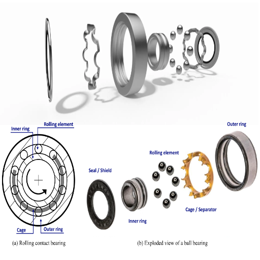
Q: What is the purpose of the cage in angular bearings?
A: In angular contact bearing, the balls tend to clash without separation, therefore the roller angular contact bearing cage is constructed to both support and distribute the balls to avoid overload of contact with balls. This is beneficial since the system has less heat generation and wear, allowing high-speed levels for the bearing.
Q: Is it possible to undertake angular contact-bearing operations under mixed loads?
A: The bearing can sustain axial and radial loads as preloading axial loads. Because of the raceway configuration and contact angle, this bearing uniquely accommodates both radial and axial loads.
Q: What advantages can be achieved by integrating pinch-clamps on spindle bear application high-speed high-precision bearings?
A: Introducing high-precision bearings further enhances spindle application revolution speed and increases the performance characteristics of spindle performance, which is why high-speed681 and high-precision601 applications could be expected to improve.