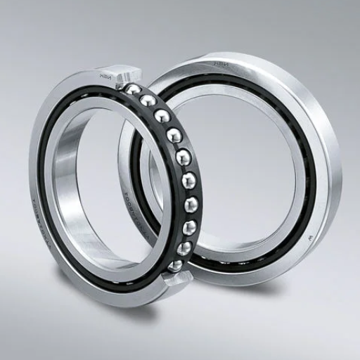
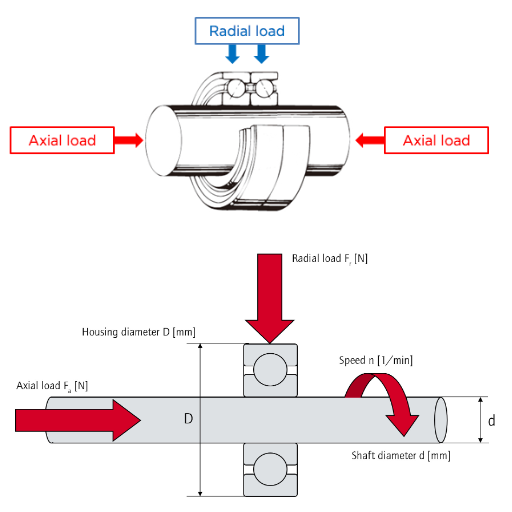
Due to their capacity to bear axial and radial loads, they are classified as intelligent bearings and indispensable mechanical elements in engineering and machinery. Their other distinctive feature is that they are specially designed to have angular contact geometry. Such features make the bearings suitable for highly precision demanding applications with complex loading requirements. These bearings are not only required in high-speed motors but also robotics as well as in industrial machinery. This article illustrates the specifics of single- and double-row angular contact ball bearings in terms of their design aspects, working principles, and significance in their respective fields. By the end of the article, the reader will fully understand the implications of angular contact ball bearings on contemporary innovations and their usage in mechanical devices.
What are the key features of angular contact ball bearings?
How does the contact angle affect performance?
The first aspect I pay attention to when I rate the performance of angular contact ball bearings is the contact angle. According to Wright, the conformity coefficient, one of his many ways to characterize the contact angle in bearings, directly relates to the ability of a bearing to support axial and radial loads. Just as the geometry of the protective lip varies, so do the contact angles in lip seals; those employed on zippers could differ from 30° to 40° and are more suited for the flotation of machine tools or high-thrust motors. Conversely, faster contours usually have low contact angles, generally around 15°, and do better on radial loads. They will maintain the levels of precision and stability needed on high-speed spindles.
Bearings working with contact angles other than those of 90 levels can also affect the speed of rotation of the bearing as well as its accuracy. For example, a smaller range of angle of contact not only enhances the miniaturization of contact but also generates less heat during the process of rotation, which helps prevent damage at high speeds. On the other hand, these designs will likely have difficulties with high axial loads where a greater angle of contact gives more support. I usually advise using duplex wrench arrangements to ensure an optimal initial contact angle for more incredible loading environments, which can help tailor pre-load situations and increase circumferential rigidity.
A Bearing’s contact angle aligns the purpose of the bearing with the specific application. The decision is based on the direction of load, speed during the operation, and the degree of accuracy required. For instance, in such systems where bearings are set at 15-degree angles, the usual limit is around 10 thousand RPM, which depends on the choice of materials used and lubrication. With the containment angle clearly defined, I can determine an optimal position that meets the technical specifications while safeguarding the expected design and ensuring efficiency.
What are the differences between single and double-row designs?
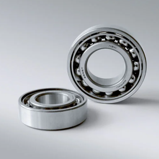
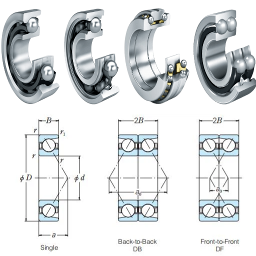
In bearings, row, and double-row angular contact ball bearings also differ. That differs from angular contact ball bearings, which are also radially symmetric. The first thing that I analyze in the differences is the way of their structural design because that is how they work. Single-row bearings are made to accommodate combined axial and radial loads but only in one direction. I must combine them with another bearer to use them in two directional axial load applications. For example, their small dimensions, coupled with their ability to attain higher RPM in rotary motion, make them suited for high-speed spindles or gearboxes when there is a need for greater accuracy.
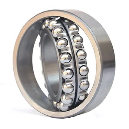
Now, let’s compare double-row designs. They are two single-row bearings mounted back to back, forming a double row, and can withstand axial loads in both directions without requiring an arrangement to create a pair. This efficiency is handy for applications where space is tight yet robust load capacity is needed, such as in pumps or conveyor systems. This also results in a minimized rotatory displacement relative to the installing surface. The installation of the double-row variants thus saves time and reduces the overall complexity of the entire system design since two bearings are used inside of one cabinet.
One major factor in determining the technical classification of these types of bearings is their load capacity, and the Other is their rigidity. Single-row bearings generally have contact angles that range from 15 ° to 25 ° with a trade-off between speed and load. In contrast, double-row bearings are designed to handle higher combined loads but, on the downside, compromise on the speed of performance. Their stiffness also assists in better system stability, which is essential in situations with high chances of a system being misaligned or highly stressed. Equipped with this understanding, I can have an appropriate design of a bearing that will suitably meet these specific application requirements.
How do angular contact bearings handle combined radial and axial loads?
The geometry of the Dn bearing determines the design in such a way as to know how, if at all, the angular contact bearings can handle axial and radial loads. These bearings have an angular contact position between the raceways and rolling elements, which is not more than 5 5 degrees, though most are 5 15 and 20 degrees. This contact angle allows the bearing to apply forces on the assembly at an angle to allow the bearing to be able to assist in handling radial loads while permitting the axial load to be applied in one direction. This feature is why I mainly use them in most precision machines, such as CNC spindles and high-performance motors.
The load distribution relies strongly on the contact angle of choice. For instance, a larger contact angle of 25° or 40° tends to promote more axial load orientation, which is helpful for thrust-dominated applications like pump shafts or screw compressors. On the other hand, an easier contact angle of, for instance, 15° favors radial load directional motion and is more appropriate for high-speed applications. Thus, in the case of a high-speed gearbox, a smaller angle will promote better motion while maintaining focus on axial support to curb excessive heat generation.
From an application point of view, one of the arrangements I usually use is the duplex arrangement, that is, back-to-back (DB), face-to-face (DF), or tandem (DT), to dictate the load-carrying direction and stiffness. For example, in very high axial and bending conditions, the back-to-back arrangement improves load stiffness in both axial directions, making them ideal. It is technically possible to improve bolt tightening and lubrication patterns to enhance the material’s performance by reducing wear in a lovely time. Such realizations enable me to reconfigure the conditions to achieve the best performance across multiple engineering applications.
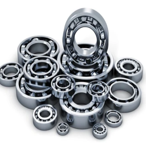
What types of angular contact ball bearings are available?
What are the advantages of single-row angular contact ball bearings?
It should be noted that when it comes to single-row angular contact ball bearings, the most pronounced aspect for me, which I consider their most important feature, is their capacity to support combined axial and radial loads. Such bearings are used in applications requiring high speed and precision, such as electric motors, pumps, gearboxes, etc. Primarily, they are manufactured with contact angles of 15°, 25°, or 40°, which allows for the adjustment of the angle contact to achieve better speed or increased load capacity. Specifically, a 15° angle is standard for high-speed machines for which friction and accuracy are paramount, whereas, on the other end of the scale, a 40° angle is more suited for applications requiring large amounts of axial load to be taken.
The compact design of these bearings thrills me in single-row designs. Their smaller size than double row options make them perfect for systems where conserving space is essential without compromising performance. Undoubtedly, even with their compactness, these bearings are remarkably accommodating. Particularly, physically separating the appropriate pairs as back-to-back or face-to-face arrangements enables the bearings to absorb axial loads directed in opposite directions, significantly improving system rigidity, which is helpful in machine tool spindle and industrial fan configurations.
From a technical point of view, single-row bearings are less tedious to lubricate and align. They also often accomplish operational speeds exceeding 10,000 RPM in exact configurations combined with adequate lubrication and low-friction materials. Their uncomplicated design decreases the ease of installation, making them cheaper and more reliable. I have found such bearing types to be exquisitely adaptable, precise, and able to perform remarkable functions across various engineering projects, irrespective of whether it is a high-speed bearing or one for moderate load applications.
How are double-row angular contact ball bearings different from single-row?
The first difference between double-row angular contact ball bearings and single-row designs is their capability to accommodate axial loads in both directions. The need for pairing is eliminated when combining two single-row bearings arranged back to back into one unit, single-row bearings. This makes them inherently better for use in applications such as industrial pumps, compressors, and material handling equipment, which require support of bi-directional axial loads because they are strong. Because of the double-row configuration, the amount of space needed and the installation difficulty are less, making it suitable for smaller systems.
In a functional comparison, it can be stated that double-row bearings can withstand larger magnitudes of combined load than single-row bearings. Single row bearings work better in high speed applications with great accuracy, however, it can only be used in pairs which must be configured in such a way that they can withstand axial load in both directions. In contrast, double-row bearings have greater strength and rigidity, making them useful in places with high chances of misalignment or vibrations. For instance, I prefer to use double-row bearings in machinery like conveyors or agricultural equipment as they provide excellent reliability when working under harsh conditions.
Looking at the technical side of things, the contact angle in double-row designs is relatively slight in the 25° to 30°, which aids in a somewhat equal distribution of the axial and radial loads. Double-row bearings are complex in design and thus may not be able to reach as high speeds as single-row bearings. Still, they can compensate with their versatility in load bearing and long-term functional lifespan. Hence, by evaluating the need for a particular project, it will be possible to conclude whether gaining speed on a given application is worth the tradeoff on double row designs and their survivability and performance.
What are 4-point contact bearings, and where are they used?
A 4-point contact bearing has always fascinated me with its granular construction and the ample amount of applications it has. They enable the support of axial loads in either direction and are a singular type row of a contact ball bearing. The geometry of raceways allows the design to have two contact points on each side between the balls and the raceway. Such a structural notion is known as four-point contact, and this concept enables the bearing to support a four-point load while also allowing space efficiency. They come in handy when an increased double row or combined bearing application isn’t possible due to a system’s limited axial and radial forces.
I have encountered situations where four-point contact bearings have never let me down, specifically while dealing with slewing rings and robotic arms. Due to their ability to withstand masses while compact, they can support bi-directional loads, making them ideal for such tasks. Moreover, I have also used them in turntables and gearboxes where a bearing was simplified, yet its performance could be sustained. They are also widely used in the aerospace industry as they tend to be lightweight yet can handle a considerable load.
Regarding engineering, I have encountered four-point contact bearings wherein the nominal contact angle is between 35 and 45 degrees. This means these bearings can resist a more significant proportion of axial load than the radial load. The raceways, however, persistently have a cut or notch to accommodate many balls in the bearing, which further increases the load. In turn, the four-point design is optimal; however, there is a catch: specific alignment and adequate lubrication in managing the four-point design because it is sensitive to misalignment. Nevertheless, while using them in large quantities of engineering projects, I can be sure that all projects will start working efficiently and have a fair lifespan.
How do angular contact ball bearings support different load directions?
Is it possible for angular contact bearings to exert axial loads in both directions?
In a typical working scenario, it will not be easy if I require bearings that can transmit axial loads in both directions and are standard single-row angular contact bearings. Specific configurations, like the back-to-back or the face-to-face arrangements, are required in this case. A single-row type can only withstand axial loads in one of the directions, as its contact angle is explicitly set between 15 – 40 degrees. However, by strategically stacking two of these bearings, it is made possible to withstand axial forces in both directions. Such a feature makes it ideal for deployment in those areas where both stability and load sharing capacity is necessary for success, spindles in machine tools or high-performance gearboxes are good examples.
For me, at least, double-row angular or four-point contact bearings are more effective as they can support bidirectional axial loads. I use them if i require a myriad of double row angular contact bearings. Double-row bearing designs are two single-row bearings joined together, allowing for relatively small axial loads to be handled in both directions. An ideal case study is in conveyor systems or agricultural machinery, where fluctuating loads are standard. Space and time are often a constraint in these scenarios. Four-point contacts work just as well, if not better, in cases like these. They are situated on robotic arms or rotary tables.
The geometry and material accuracy of these bearings are fundamental to their success. Double-row and four-point contact bearings are provided with optimal contact angles ranging from 25° and 45°, which perform load optimally. Good alignment of the contact parts and applying lubricant grease are prerequisites for efficient operation. Otherwise, slight angular deviation could cause degradation of the device’s performance or excessive wear of its parts. I select and configure the bearings according to the application’s requirements so that the systems can be expected to work reliability even if the bearings are subject to heavy loads.
What is the load capacity of angular contact ball bearings?
As I assess the load capacity of angular contact ball bearings, I appreciate that they are greatly affected by the contact angle, internal geometry, and materials used to make them. These bearings were developed to handle both circular and thrust loads but have limited capacity by the beam strength of their contact angle. For instance, an axial load can be applied to an angular contact bearing with a contact angle between 25 and 40 degrees. In contrast, small bearing angles promote high-speed bearing use but with low axial load. The balls’ size and the raceway’s design are also crucial because large bearing diameters meant large balls and significant loads.
The first thing that comes to my mind is whether the bearing is a single or double row. Single-row bearings can endure quite a radial and axial load in one direction. Still, it enhances their combined capacity to withstand axial loads in both directions when used in a back-to-back or face-to-face configuration. However, it stands to reason that bearing arrangements of this type are never used because, for a one-row design, a single axial bearing suffices since it can withstand significant double axial loads. On the other hand, double-row bearings are found in pairs, enhancing their load capacity and making them suitable for pumps, turbines, heavy gearboxes, and any other devices that require proper load management.
From a technical standpoint, angular contact ball bearings typically have three load ratings, namely dynamic, static, and combined load rating. For instance, a variable frequency drive center bored bearing with a 30 mm hole will typically have a maximum load between 20 kN and 12 kN depending on the static load and its manufacturer, respectively. Adequate fitting, placement, and sufficient lubrication of these bearings are essentials since they help to utilize the full load-bearing capacity of the bearings. I also ensured I understood these specifications in detail and could deliver bearings that would suffice for the most complex engineering projects.
What is the maximum speed that the above bearings can perform?
Angular contact ball bearings always receive praise from me when we address high-speed and performance issues. The design features a certain contact angle between two of the surfaces (usually between 15° and 25° in high-speed models) that allows them to receive both radial and axial loads while still permitting high speeds to be achieved. Because of the optimized internal structure and reduced friction, these bearings can have high rotation speeds and achieve more or less precision, which is essential in turbines, CNC spindles, and electric motors.
Another vital aspect of these materials is their quality and lubrication systems. For example, the heating issue can be overcome by constructing bearings with ceramic balls instead of steel ones, which are lighter with less friction, preventing them from spinning faster. High-performance greases or oil-air lubrication systems in conjunction with these bearings would limit the thermal effects, which enable the bearings to operate efficiently for longer durations. Furthermore, some manufacturers specialize in precision-level products such as ABEC 5 or ISO P4, ensuring the bearing has adhered to less-than-ideal circumferences required for high speeds.
Rotating systems that require high speeds, such as jet engines, medical centrifuges, or high-frequency spindles, are high in friction and thus require angular contact bearings. However, I have never failed to note their blocking speed ratings, which range over 20000 RPM. Finding the suitable rated speed on the model always helps ensure that the bearings are coupled with the fitting housing, preload, and alignment to be reliable and effective in specific applications.
What are the benefits of using duplex angular contact ball bearings?
What does the back-to-back orientation in duplex bearings entail?
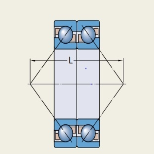
In my understanding, the contact angles of the bearings are not parallel, instead they “V” as the axes are back to back when I set up the bearings in a back-to-back arrangement in duplex bearings. This is referred to as the “angular contact bearing O” configuration. It is pretty preferable in applications of dual fitting of the bearings. It works within strict tolerances, ensuring the simultaneous passage of radial and axial loads relatively efficiently. From the contact angles, it can also be seen that the bearings can easily cancel out the forces applied to either end, making it easier to tilt or rotate the shaft without the risk of the bearings failing in high-stress environments.
The assembly tends to offer excellent support no matter how vigorous the installation or orientation of the shaft and machine is due to its ability to withstand deflection under load, which includes heavy loads. As the lines of the load are directed away from one another, a high radial and axial load is present in the assembly, ensuring high stability. This permits the usage of this assembly in sensitive components as it is widely used in spindles, pumps, and gear drives, as it can reduce the stress on the unit, ensuring smooth action.
From a technical standpoint, the back-to-back arrangement sometimes even calls for a preloading adjustment to satisfy their loading conditions. Depending on the system requirements, such tolerances are matched to selected pairs of bearings, or a shim is used. Furthermore, placing bearings apart increases the structural stability of the system and, thereby, its load-bearing capacity. By strategically selecting and working around the back-to-back configuration, I aim for the reliability and durability of the machine, even if it is expected to be high-performance.
What is the effect of preload on the duplex bearing performance?
For duplex bearing performance, one has to consider preloading, which I think is one of the most essential elements. Preload is the axial force that is applied to the bearings during installation. It removes internal clearance and ensures the rolling elements always contact the raceways. This increases stiffness, extends the life of the bearing, and improves any application that requires high precision. Preload is very important in operating CNC machines, medical imaging, and aerospace equipment because it prevents vibration problems and reduces deflection of the parts when subjected to load.
I have noticed that the suitable preload differs based on the application’s working environment. For example, a low preload reduces friction and heat, which is favorable for applications that involve high speeds or low axial loadings. However, a large preload improves stiffness and dines the system, which is suitable for applications subjected to large shock loads or with precision alignment characteristics. As a rule of thumb, preload values are determined using parameters such as axial compliance, bearing configuration, namely back-to-back, face-to-face, or tandem, and loads that will be put on the system.
Spring, spacers, or, if necessary, “bearing pairs machined to now ” dimensions can be used to apply the preload. But, since I am also interested in optimal adjustment marks, unnecessary marks can cause movement instability or overheating/increased wear in addition to bearing failure. Chances of balancing these factors make most parts of bearings perform remarkably functionally as required in most unforgiving engineering applications.
What are the design considerations for angular contact ball bearings?
In what ways do the inner and outer raceways influence bearing function as a whole?
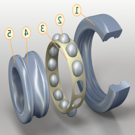
I think shaping the raceways – both the inner and outer of the angular contact ball bearings – is very important. These raceways are constructed as the surfaces where the balls roll and are manufactured to keep the contact angle unchanged. This allows the bearings to take on radial and axial loads. For instance, the design of the raceways is to reduce friction and transfer pressure evenly over the balls to avoid excessive wear on specific areas and enhance sustainability. These geometry properties enable angular contact bearings in devices such as machine tools and high-speed motors.
The load-carrying capacity is directly proportional to the alignment of the inner race and outer race bearings. The diverse raceway angles have an ideal design that helps in the axial deformation of the loads incorporated by the bearing, thus allowing it to bear combined loads. For example, larger angled raceways, such as 30 and 40 degrees, perform better for axial load bearings, while a 15-degree contact is best for high radial loads at high speeds. I’ve observed that kind of flexibility in devices like compressors where the load goes from higher to lower and vice versa. These raceways are in contact with the preload, which increases the stiffness and removes the clearance so that the working of components is still effective and smooth even in extreme conditions.
The performance of the bearings is further optimized by the selection of materials and the surface treatment of the raceways. Curbing the exposure of the bearings to wear and corrosion and using high-hardness steel or ceramic materials for the raceways will increase the load the contact surfaces can take. Many designs have also adopted polished surfaces to decrease friction, heat, and vibration during motion. Given the understanding of the operation of the inner and outer raceways, I am confident that all devices, from advanced precision robots to robust industrial machines, can have practical functionality without any issues.
How important is the outer ring for bearing function?
While assessing the durability of angular contact ball bearings, the outer ring is critical in maintaining load balance and ensuring the bearings’ overall functionality. When rolling elements are in contact, they form a contact surface that facilitates the force transfer from the bearing to the housing assembly. Their radius and contact angle with the raceway are primary shaping features determining the bearings’ efficiency in withstanding axial and radial loads. For example, turning the outer ring correctly ensures that load shifting occurs without sudden increasing local pressure being established or uneven wear occurring, which can disturb function, for instance, in high-precision electric motors or CNC-controlled spindle machines.
The outer ring also acts as one of the centering components for the bearing relative to the bearing housing. When considering properly designed outer rings, it is noted that they strengthen the assembly and ensure that the balls are in contact with the inner and outer raceway at all times. This contact requirement is even more critical when the bearing rotates at high speeds or carries heavy loads. For example, in systems prone to misalignment or vibration, such as automotive gearboxes or industrial pumps, the design of the outer ring helps avoid distortion. It, therefore, enhances the performance and longevity of the bearing.
The outer ring’s performance has also increased due to advancements in materials and finishes. High-strength steel or ceramics help the outer ring withstand tremendous loads and heavy wear in extreme heating conditions, while clean surfaces eliminate heat caused by friction. Some designs also call for outer rings fitted with lubricant relief grooves or channels to enable smooth action over extended operations. I emphasize the need to concentrate on the outer ring’s performance and quality so that the bearings work effortlessly and ideally, even in onerous operating conditions.
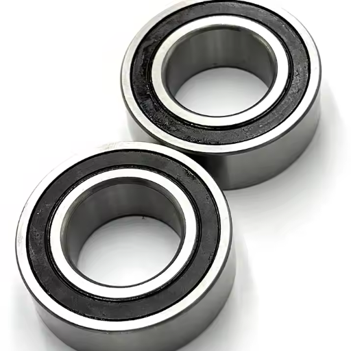
Are there sealed angular contact bearing options available?
Sealed angular contact bearings are helpful when I need to guarantee anti-contamination protection or enhance lubrication retention. These bearings are designed with external seals covering their rolling elements with the raceways to protect them from dust, moisture, or any other external debris. Such features add to ease of operation and tend to minimize maintenance requirements, making them extremely useful in contamination-prone environments such as food handling equipment, textile manufacturing, or outdoor conditions.
Sealed angular contact bearings are already lubricated before performing in a consistently lubricated atmosphere for their operational life. This alleviates the need for routine relubrication, which is a great benefit when maintenance is complex. In most standard applications, seals fabricated from nitrile rubber or fluoropolymer are common. These seals help maintain the temperature while allowing efficient lubrication. Most sealed bearings can efficiently operate between -40 degrees and 120 degrees Celsius, but this also varies according to the seal material and grease being used.
Another thing that I consider is the operating speed of the bearing, as I have found sealed bearings to be very useful, added to its design, and not solely to provide protection. Let’s say high-speed spindles or precision pieces of equipment help achieve constant performance and minimize the chances of grease leaking by keeping the inner environment clean. I can even ensure improved downtime and enhanced operational reliability by sealed angular contact bearing selection in heavy industrial environments.
Frequently Asked Questions (FAQs)
Q: What are the main characteristics of angular contact ball bearings as a type of rolling bearing?
A: As one of the members of the ball bearings family, radial and axial loads are applied to angular contact ball bearings simultaneously. Angular contact ball bearings are designed to restrain the movement of raceways in the inner and outer rings displaced in the axial direction of the bearing construction. Thus, they can support a unidirectional axial load and rotate at high speeds better than other types of bearings.
Q: How do single- and double-row angular contact ball bearings differ?
A: It is important to note that single-row angular contact ball bearings only permit the application of axial load in one direction, while their double counterparts, double-row angular contact ball bearings, permit the application of the axial load in both directions. It was also found that double-row bearings have greater load-carrying ability and applicability in areas with heavy combined loads. On the other hand, the single-row bearings have a smaller profile and can be used in locations that use high speeds.
Q: What are the typical applications for angular contact ball bearings?
A: Angular contact ball bearings are utilized in different areas, such as machine tools, gearboxes, pumps, and electric motors, among others, as they are used at very high speeds and in applications where loads in both the radial and axial directions must be supported. These bearings find most applications in precision-engineered equipment, automotive transmission systems, and industrial machines where precision and dependability are essential.
Q: How does the contact angle affect the performance of angular ball bearings?
A: The performance of angular ball bearings is dictated mainly by the contact angle of the bearing, the wider the contact angle, for example 35 degrees, the more axial load the bearing can withstand but the bearing’s radial load capacity will be lower. However, the case of miniature contact angle bearings is the opposite; they handle a relatively larger radial load capacity but reduce axial capacity. The application and requirements dictate the specific contact angle, especially on the ratio that axial and radial loads must be supported.
Q: Can angular contact ball bearings be employed in pairs?
A: Yes, pairs of angular contact ball bearings can be arranged in back-to-back or face-to-face positions. This arrangement provides higher stability with the increased load capacity of the assembly. These paired bearings can take the load in both axial directions, making the structure more rigid. This configuration is typical in rotary spindles for machine tools, which need higher precision and stiffness.
Q: Do angular contact ball bearings increase the bearings’ performance in high-speed conditions? If so, then how?
A: It has been observed that angular contact ball bearings see to it that the performance of the bearings can be sustained or improved even at high speeds, and this is possible because of their design. As the angle is increased between the balls and raceways, the speed is proportional, which decreases the friction and heat generated, allowing a smoother operation once the high speeds are hit. These also provide ease of manufacture of bearings using high precision and unique materials, such as ceramic balls, thus increasing the working life of the bearings in such extreme high-speed conditions.
Q: What benefits do angular contact ball bearings have in gearbox situations?
A: In gearbox applications, angular contact ball bearings offer several advantages. They are capable of transmitting the combined radial and axial loads that are common in gearboxes. Their capacity to take on thrust loads ensures that the gears are correctly aligned to minimize wear and increase efficiency. This bearing type also increases the requirement for gravimetric applications of high precision rotation and high speeds, such as in the construction of modern gearboxes that aid in system performance and reliability.