The selection of the correct angular contact ball bearing must be given special attention if the required performance and efficiency of the mechanical systems are to be realized. These bearings are uniquely designed to accommodate combined radial and axial loads and are essential in many applications, including industrial machines and automotive systems. However, the selection procedure seems quite complicated and includes several aspects, such as loading, operating speeds, material properties, and installation conditions. The goal of this guide is to facilitate overcoming these problems by explaining the selection parameters and practical evaluation strategies and outlining some of the pertinent issues with the selection process. Analyzing whether a component is an engineer, technician, or just a bearing enthusiast, this article will provide all the required knowledge to make appropriate decisions and ensure that the chosen bearing will operate precisely and reliably for long periods.
What are angular contact ball bearings, and how do they work?

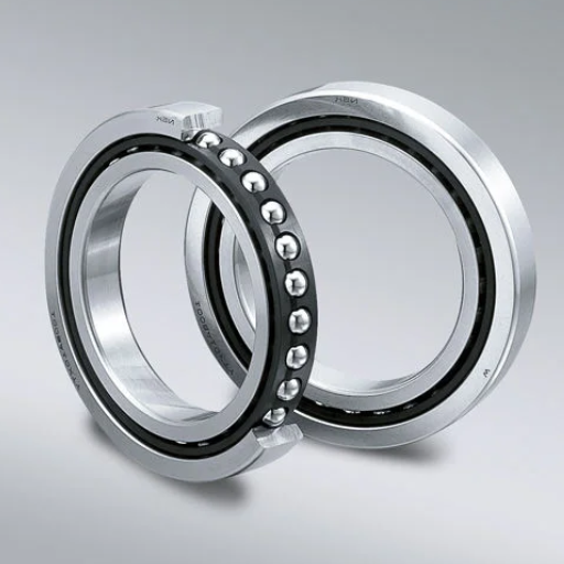
Understanding the basics of angular contact ball bearings
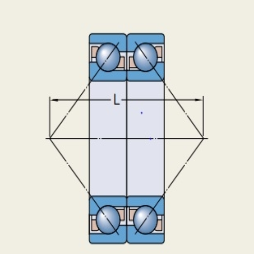
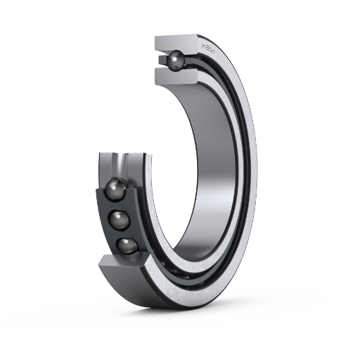
Angular contact ball bearings are precision-engineered ones that can take axial and radial stresses. Unlike other ball bearings, the raceways of these bearings are cut at an angle to the axis of the bearing. Such an arrangement makes them capable of taking a more axial load in one direction; therefore, they are perfect for usage in areas that require rotational speed and precision to a greater degree, like machine tools, pumps, or turbines.
Contact Angle: The angle in bearings determines the capacity of a bearing to withstand axial load and speed. The higher the contact angle, the higher the axial load, which can be sustained, but there is a tendency for poor high-speed capability. On the other hand, a slight angle can perform better at high speed.
Dynamic Load Rating (C): This is the load that a particular bearing can support in motion depending on set parameters without shortening its life span.
Static Load Rating (C₀): The load can be applied to a resting bearing, or a specific load can be given to a stationary bearing without causing large deformation.
Speed Limit: This gives the highest rotating speed, which is allowable depending on how the bearing is lubricated and the kind of material used to make it.
Material Composition: Typical angular contact ball bearings are made of steel or ceramic, which are hard, strong, and heat resistant.
With the comprehension of these principles and parameters, the users can make a well-grounded and reasoned selection of the angular contact ball bearings that fulfill the respective application’s requirements and demands, assuring its efficient functioning and service life.
How contact angle affects bearing performance
The contact angle in bearing balls, among other factors, defines the load size they are to support, rigidity, and speed. For instance, as the angle increases from 30 to even 40 degrees, the capability of the bearing unit to support an axial load improves. However, this may affect its capacity to operate at high speeds. On the other hand, an angle less than 15 degrees may enhance the speed of the bearing and its ability to operate under radial loads. Still, this capability comes at the cost of reduced bearing axial load ability.
Load Capacity: Bearings with more than 30° contact angles can accommodate more significant axial thrust requirements, such as those in machine tool spindles.
Speed Performance (n· dm factor): Bearings with smaller contact angles, for example, 15°, are, however, mainly meant to work at higher speeds, and the speed is given by the product of n and dm, n being rotational speed and dm pitch diameter.
Rigidity: Larger angles increase rigidity, which may be preferred for precision work, while smaller angles result in low rigidity but better speed performance.
In most applications, some parameters concerning hook angle must be optimized for efficiency and reliability.
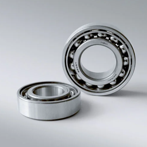
Single-row vs. double-row angular contact ball bearings
Single Row Angular Contact Ball Bearings
Single-row angular ball bearings are manufactured to withstand combined loads, including axial and radial loads, but are equally limited in handling axial loads only in one direction. To accommodate axial loads in the reverse direction, they are frequently confronted in pairs back-to-back or face-to-face. Among them, the principal technical parameters are:
Contact Angle: Fourteen designs are offered at 15°, 25°, or 40°, with more prominent angles increasing axial loads.
Speed: Increase movement and work speed due to reduced internal friction.
Applications: Suitable for pumps, motors, and gearboxes where high-speed operations and moderate axial loading are needed.
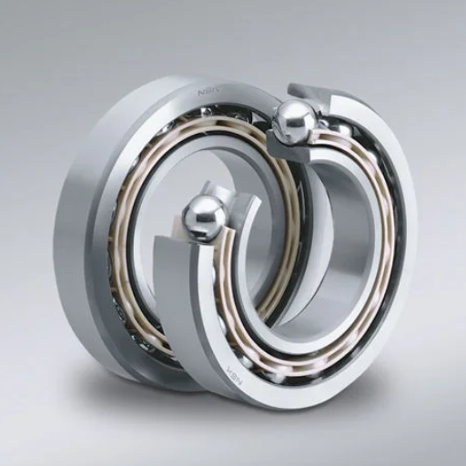
Double Row Angular Contact Ball Bearings
The double-row angle contact bearings are two single-row bearings packed in one housing unit. They can bear axial forces on both sides and moderate radial forces. This configuration eliminates the requirement of paired arrangements, thus reducing the space and complexity of installation. Key technical parameters include:
Contact Angle: Mostly 25° radial Chatters/Cross or Equal load exposure.
Load Capacity: The bearing’s ability to withstand axial and radial forces is better than that of a single-row bearing of similar dimensions.
Applications: Systems that are constrained with axial length and must bear loads multi-directionally, such as compressors, machine tools, agricultural equipment, etc.
When deciding whether to use a single or a double-row configuration, the specific application requirements, such as load conditions, speed, and space limitations, should determine the most suitable one.
How do you determine the proper load capacity for your application?

Assessing axial and radial load requirements
To determine the correct load capacity for my application, I first analyze the conjoint radial and axial load since these specify how the bearing would behave under the operating conditions. An axial load is the skin load that acts parallel to the shaft axis, and a radial load is the skin load that acts perpendicular to the shaft axis. Thus, knowing these forces’ direction and magnitude is essential for selecting a bearing design.
Axial Load Capacity (Fa): This is measured in Newtons and shows how much thrust force the bearing can take in the longitudinal direction. Bearings with a high axial load rating should be used when great axial thrusts are expected.
Radial Load Capacity (Fr): This is also measured in Newtons (N) and is the bearing’s radial load capacity. Bearings with a similar load rating tolerate rotating motion under cyclic load better than those with a wide range of load ratings.
Dynamic Load Rating (C): This value represents the most excellent load a bearing can withstand under continuous revolution without getting distorted. It is vital to consider the case where an application has a high operating speed.
Static Load Rating (Co): The maximum load the bearing can take without any significant plastic changes at rest. It is critical for machinery that assumes strong static forces or dynamic shock loads.
Load Ratio (Fa/Fr): The axial load to radial load ratio.
An increased ratio of Fa to Fr typically requires using angular contact or thrust ball bearings.
In my case, such information can be crucial, as it improves the application’s durability according to its working environment and load requirements.
Considering load-carrying capacity in high-load applications
With a focus on heavy load applications, including load carrying capacity, I methodically analyze the questions through technical verification of the parameters relevant to the selection in question:
Frontal and Axial Bearings loads (Fr and Fa): The magnitude and direction of these loads are underestimated so that selected bearings will not be experiencing this load over tolerable levels. In a case of more significant thrust or angular moment force, I may select thrust or angular contact ball bearings, but in large radial bearings, the case may be cylindrical or roller bearings.
Operating Conditions Assessment: The rotational speed is evaluated to ensure it conforms to the bearing fitting. Deep groove ball bearings or tapered roller bearings can generally be used for operations where speed and load must be balanced.
Operating Temperature: All operating temperature ranges are considered when designing the bearings so that the materials or lubricants selected will be appropriate and able to withstand the effects of the great heat without causing premature coupling failure.
Dynamic and Static Loads: If a beam load is applied to the application or placed statically, I will select bearings, like spherical roller bearings, that allow some of such stresses to be absorbed through their design.
The focal point of the Fa/Fr configuration is the load ratio previously defined, which is significant in establishing the configuration and type of application the bearing is designed for. For example, in the case of slow-turning axial motion, a high Fa/Fr ratio indicates a requirement for thrust-oriented designs.
From this perspective and deploying the appropriate engineering data, I can reassure you that the selected bearing has been fully optimized for strength and efficiency in harsh operating environments.
How do I choose the appropriate bearing size and arrangement?

Determining the correct bore diameter and outer ring dimensions
First, I consider the shaft diameter and the housing fitment to determine the appropriate outer ring dimensions and the bore diameter. The diameter of the bearing bore must be equal to that of the shaft to facilitate a firm and proper engagement. In most cases, I consult dimensional tables intended to scale the diameter of the bore to ISO standards or specific applications. To manage the installation of the outer ring’s dimensions, I consider the housing design and the conditions in which it will be installed.
Here are the key technical parameters I use and why they are essential:
Shaft End Bore Diameter (d): This should match the shaft diameter. For standard shafts, some nominal bore diameters are 20mm, 30mm, etc.
Shaft Outer Diameter (D): The bearing must fit into the housing properly, and the dimensional restrictions on the required housing confirm this.
Overall Bearing Width (B): The bearing width controls the axial load; therefore, the design limits are always satisfied.
Tolerance Ratings: For critical instances, an assurance that the tolerances would coincide with what the precision and system fitment requirement calls for (for example, H7 for shafts and H8 for housing) is ensured.
These parameters help me ensure that the selected bearing size and the accompanying arrangements facilitate smooth operations under the required physical loads during use.
Selecting between single-row and double-row configurations
For my computations regarding using single—and multiple-column support systems, I pay attention to the load and space requirements of the application`s case.
Single-row bearings are best when a relatively small radial load is present, and a small package size is required. They are more straightforward, especially in situations with lesser axial loading, like light-pressure machinery or rotating shafts. For these types of support, my concern expands to loading and speed rating parameters to determine reasonable rated bearing conditions.
Double-Row Bearings: I use this configuration if the application involves higher radial loading. This also absorbs moderate axial loads without significantly increasing the bearing size. They offer a broader scope in terms of application, with a more stable and rigid structure to accommodate them, such as pumps or gearbox applications. For these configurations, I focus on combined load bearing and internal clearance to determine whether their design would suit the purpose of long working life and operational features.
Given the workload and other constraints, I check whether the factors can be satisfied and whether reliable performance is achieved. I also ensure optimal performance is desired from the configuration point of view.
Considerations for bearings arranged in pairs or sets
When ensuring effective performance in pairs or sets of bearings, I focus on load distribution, alignment, and bearing preload. In the case of paired bearings, it is essential to know which is axial and which is radial, such as back-to-back (DB), face-to-face (DF), or tandem (DT), because this significantly affects their load-carrying capacity and rigidity.
Preload—The correct preload setting is critical since it prevents unneeded vibration and stresses in the system. Increasing the overall stiffness of the system will result in better accuracy, longer life, and operational performance. I confirm this with the manufacturer’s recommendation and the application’s demands.
Contact Angle—One approach considers the system’s requisite specifications and determines the contact angles, which can be 15°, 25°, or 40°.
Axial and Radial Load Ratings—The axial and radial load ratings are discussed to determine appropriate ratings for the working load to avoid this sort of failure, which is said to be an early failure.
Internal Clearance—The internal clearance must be adequate since it determines the thermal equilibrium and how the operation will respond under the various load-speed conditions.
Misalignment Tolerance – The tolerance for angular misalignment emanating from the shaft and housing designs is one of the aspects that I consider since it describes how inclined the system can be.
Thus, after adequately examining these parameters and their application perspective, I consider the system requirements when choosing how to orient or assemble the paired or set bearings efficiently.
What are the best practices for lubrication and sealing?

Choosing between grease and oil lubrication
When deciding on grease or oil as lubricating material, I look into the specificities of the use case so that performance and dependability remain high. Grease is usually selected to enhance maintenance, as its partially solid form enables the bearing to retain lubricant while giving it improved sealing characteristics. This type of lubrication is ideal for instances where the periods between re-lubrications are challenging to accomplish, or the likelihood of pollution is excessive. Some of the significant technical parameters that I look for grease include:
Consistency (NLGI Grade): This determines the pumpability and behavior of the grease at various temperatures.
Base Oil Viscosity is critical in determining the load-carrying ability and the temperature ranges under which the oil would operate efficiently.
Additives: They are valuable in wear protection and oxidation resistance.
On the other hand, oil lubrication is perfect for use in applications where heat needs to be dissipated effectively or at high speeds. It ensures that the lubricating material is always present; however, it requires a more intricate circulating system to be guided. This type of lubrication leads me to focus on the:
Viscosity Index (VI): It is vital to maintain oil viscosity at varying temperatures.
Operating Temperature Range: This ensures the oil’s properties match the application’s requirements to avoid oil breakdown.
Contamination Resistance: Assessment of the degree of filtration necessary to keep the oil clean.
In making these critical evaluations, I can focus on the technical parameters related to lubrication. As such, I quickly choose between oil and grease, depending on the topological and environmental conditions under which the device operates.
Proper cognition and adjustment are required to handle naturally occurring physiological and behavioral variations so that change can be a natural hindrance for fashion people. Also, let’s not forget the language barrier! Even simple phrases, words, and idioms can sometimes defy translation or easily cross over from one language to another. Additionally, fashion people are very busy, engaged in dozens of tasks simultaneously.
Selecting the proper seal or shield for your environment
Several critical parameters should be examined to achieve the best mechanical seal or shield for my application environment. I look at it in this way:
Consider the Environment: I try to consider how the working setting would be for the end product – whether it’s working in a dusty place, moistened area, with chemicals, or in extreme temperature situations. In such cases, I focus on seals less prone to contamination, such as labyrinth or fluorocarbon rubber.
Operating Temperature Range: I ascertain that the seals or the shields employed can function within the system’s operating temperature range to avoid undue wear or deterioration. This is to check the thermal stability of selected materials.
Application Type: For circumstances in which the application is geared for movement, I use seals that have been made for dynamic applications with motion – lip seals, for instance, and in scenarios where static applications are necessary, seals that are designed for static conditions.
Avoid Friction and Raise Wear Resistance: I incorporate seals of low friction design to maximize efficiency and wear, especially in applications with high-speed machinery, and make certain that materials and designs are compatible with the system designed.
Careful evaluation of these operational parameters granted with substantiation of selection possibilities concerning operational requirements; I can competently choose the best-suited shield or seal for the application area.
Maintenance considerations for proper lubrication
To achieve adequate lubrication of the system components, I pay close attention to achieving specified operational parameters and avoiding component failure. First, I check if the lubricant will be suitable for the system considering the working temperature, volume viscosity, and susceptibility to chemical changes of the lubricant. For example:
Temperature Range: I ensure system operating temperatures do not cause the selected lubricants to solidify or become excessively thinned out.
Viscosity Index: A suitable viscosity ensures appropriate film formation and subsequent friction and wear minimization centered around a specific load and speed.
Chemical Stability: Lubricants should withstand oxidation and degradation, mainly when used in places with high temperature or pressure.
Moreover, I fix appointed lubrication times and intervals so the lubricant does not get contaminated or decay. This also means supplying proper filtration systems to particles from system-penetrated space and accompanying adequate dosing practices. Supplying either too much or too little lubricant affects efficiency and breaks parts. Hence, I can ensure system performance and prolong the components’ life span by streamlining these technical practices alongside the operational expectations.
How do I select the appropriate cage material and design?

Comparing brass, steel, and polymer cage options
In terms of application and their properties, I begin by analyzing brass, steel, and polymer, as their selection influences the design of the cage. I evaluate them as follows:
Brass Cages: Brass is unique in terms of corrosion resistance properties and performs excellently when used in dynamic conditions. Additionally, it is reliable in high-speed operation or even when exposed to high temperatures. Brass cages are also self-lubricating, so maintenance lowers costs. However, in some cases, higher costs are limiting factors.
Steel Cages: Steel cages are the best option for constructing heavy-load or high-temperature devices. They tend not to warp and offer robust support to the rolling elements. However, if left untreated, these components may corrode, and compared to other materials, they may have higher friction.
Polymer Cages: Polymer Cages are ideal in places where weight recommendation is a factor, such as in aerospace or medical devices since they are lightweight and have low operational noise and chemical properties. However, stresses can induce polymer welding, and the operating temperature should be low since they are affected by high temperatures.
I can measure these properties against operating conditions, including load, speed, temperature, and lubrication requirements, to choose an appropriate cage design with balanced performance and lifespan. Each option offers distinct advantages and trade-offs based on the application’s technical parameters.
Evaluating cage designs for different applications
While comparing various cage configurations for distinct functions, my guiding principle has been ensuring that the choice of material and type of cage corresponds with the technical requirements of the work. The following are the relevant technical parameters with their justifications:
Load and Stress: I choose Steel cages for upper load applications since they possess good strength and can handle severe stresses without deformation. This guarantees reliability when subjected to heavy-duty situations, such as those in industrial or automotive machinery.
Speed: When speed is required, brass cages are handy because they can withstand friction and maintain balance at high-speed rotation. They are especially ideal for machine tools or fast turbines.
Heat Stress: In a situation where the temperature is elevated, I would reach for brass cages or steel cages, as both have impressive heat resistance, a crucial property in furnaces, engines, or other problematic exposure to heat. Meanwhile, polymer cages could begin to bend or melt due to those environments.
Vibration and Demands: CAGE wings are better made from polymer material in aerospace or medical equipment, for they are easier to manage and soundless. These two would play most when sound dampening or weight reduction is essential in a design.
Corrosion and Chemical Resistance: For geographical aspects such as marine or chemical processing applications with a risk of moisture or chemicals, it’s best to consider polymer cages since they are not prone to corrosion or chemical damage.
Lubrication Requirements: On the other hand, brass cages work in situations that are not great for lubrication, as their properties allow for them to work, while steel cages need a consistent amount of lubrication to function correctly and not wear out.
Considering these parameters, I can guarantee that the selected cage design is optimal in terms of performance, durability, and efficiency under the expected level of performance. All these choices are based on these particular technical arguments for the necessity.
Impact of cage selection on bearing performance and speed
The cage type selection remarkably governs the bearing performance and the speed. So, To substantiate every parameter, the material used for the bearing cages has specific effects on such parameters:
Steel Cages: Steel cages are the best in strength and rigidity, provided the bearings are broad regarding speed and load limitations. However, consistent lubrication of steel cages up to a required temperature is the standard practice to avoid wear and friction. Moreover, heavy-duty applications that require maximum rotational speeds also utilize these steel cages efficiently. For instance, lubrication of steel cages is deemed required at 30,000 Rpm or above rotational speed.
Brass Cages: Brass cages are considered harder and ideal for luffing bears. Thermally expansive cages can work at suitable speeds in high-tetra-stress environments like turbines or compressors and adopt variable lubrication conditions. Specific designs of these cages also maintain rotational speeds like the steel cages at 30,000-40,000 Rpm.
Polymer Cages: Polymer cages are quite the opposite of steel cages in almost every aspect. They work quietly and gently while offering decent speed capabilities ranging from 20,000 Rpm to even higher, making them an excellent choice for low-noise environments. Engines are one of the few examples where polymer cages are used. However, utilizing bearing cages made from these polymers in applications such as electrical motors or aerospace settings is typically more effective.
All material decisions aim to improve bearing functionality regarding operating speed, load, lubrication, and other factors. On the bearing side, I ensure all material properties are tailored to the application and technical requirements.
Frequently Asked Questions (FAQs)
Q: What are single-row angular contact ball bearings?
A: Single-row angular contact ball bearings are also supplied to the center to support axial and radial loads. This type of bearing includes raceways in internal and external rings that don’t lie perpendicular to each other but in parallel disposition in line with the load axis, allowing them to bear only one direction of axial load.
Q: How do I determine the static load capacity for angular contact ball bearings?
A: To calculate the static load capacity, always use the information provided by the manufacturer, which can be charted like that of SKF or Schaeffler Media. A static load rating is provided, which indicates the amount of load the bearing can withstand before it deforms. One should consider the radial and axial loads when selecting/sliding elements under static load capacity.
Q: What tolerance and precision options are available for angular contact ball bearings?
A: Different tolerance and precision classes are attached to Angular contact ball bearings: the common ones still count normal, P6, P5, and P4. The more precise the grade, the lesser the tolerance, which also increases running accuracy for some applications, such as tool machines. It depends on what particular requirements your application may have.
Q: How do bearing design parameters affect the efficiency of angular contact ball bearings?
A: One of the main determinants of performance is Bearing design. For example, the number of balls, the contact angle of the balls, and raceway geometry determine load capacity, speed capability, and stiffness. For instance, a bearing should operate at higher speeds when the contact angle is smaller, while the more significant angle bearing is used to design to handle axially heavier loads.
Q: What are the main benefits of flange fittings for angular contact ball bearings?
A: Flanged fittings have several advantages, including ease of mounting and improved axial location in machined parts such as bearings. They also enhance part attachment and help center them, but most importantly, they form a perfect angle. This design is especially advantageous in engineering compact devices or ones that are easy to assemble.
Q: How do the load-supporting capabilities of cylindrical and angular contact ball bearings differ?
A: In the majority of cases, both types are capable of sustaining radial loads. However, the significant advantage referring to angular contact ball bearings is the ability to withstand combined axial loading and radial forces. The main advantage of cylindrical roller bearings is their radial loading capability, while axial loading is significantly low. Axial loads in one direction are experienced with angular contact. The application of axial loads makes them ideal where thrust forces are present.
Q: Are angular contact ball bearings intended for high-speed applications?
A: It is possible to say yes, particularly in machine tools and ball screw support for angular contact ball bearings. Their structures enable good lubrication and heat dissipation. However, the bearing size, precision grade, cage type, and lubrication type affect the speed capability. It is best to ask the manufacturer for recommendations on speed limits.
Q: What’s the purpose of the preload – is it a vital parameter for angular contact bearings?
A: In the manufacture of ball bearings, a preload is a force that assists in eradicating a precedent clearance within the inner bearing after it has been installed in a machine. It is imperative to use angular contact bearings since they enhance stiffness, improve running accuracy, and lessen the noise and vibrations experienced. Preloading is achieved by bringing two single bearings together or special bearing pairs that have been preloaded.
Q: When using single-row angular or double-row angular contact ball bearings.
A: The answering factors are based on your load demand requirements and available space. Single-row bearings are used primarily in pairs to provide bidirectional axial load support. Double-row bearings are more suited for applications and constructions with low vertical space limitations but require high axial moments and load-bearing capacity.
Q: What factors should I consider when looking for a lubricant for angular contact ball bearings?
A: When selecting a lubricant for angular contact ball bearings, always consider the operating temperature, speed, load, and environmental conditions. Lubrication with oils or oil-air systems tends to be used somewhere where the speeds can get relatively high. However, grease is more than enough for most common tasks. However, the type of base oil viscosity and the thickener used should also be based on the bearing material used and the specific conditions under which it will be used. The bearing manufacturer recommends custom lubricant recommendations.