We present a guide about correctly mounting and dismounting angular contact ball bearings. These are load-bearing components used in different types of machines for high-speed applications. These rotational bearings are usually fitted and, when equipped with a specific pattern, called installation or assembly. These procedures are essential since failure to observe them results in underperformance of the bearings, making them less desirable. This guide is convenient in terms of performance, and we will guide you through the processes, give you some useful recommendations, and present the most critical aspects of the usage of angular contact ball bearings. It aims to provide you with the necessary skills and knowledge regardless of whether you are an experienced engineer or learning the field.
What Are Angular Contact Ball Bearings?
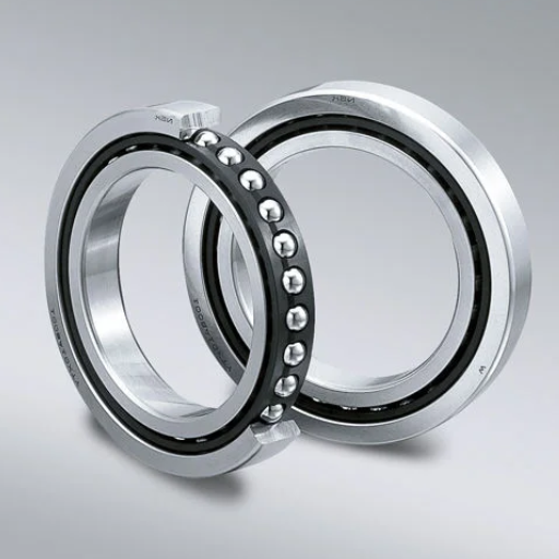
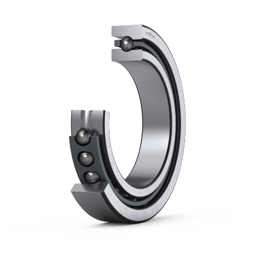
Understanding Angular Contact Ball Bearings
Angular contact ball bearings are highly sophisticated and can carry radial and axial loads. Therefore, they frequently find use in applications where loads of both kinds are applied simultaneously. According to industry leaders such as SKF, NSK, and Timken, it is crucial for these bearings that the contact angle between the balls and raceways is different and varies between 15° and 40°. This contact angle also permits the bearing to carry loads in the vertical and horizontal directions simultaneously.
In practice, factors which tend to mind at some point in time include:
Contact angle: corresponding to 15, 25, or 40, the most axial load bearing capacity of the bearing is determined.
Material: High-grade steel or ceramic material is generally used in high-speed and temperature situations.
Preloading: To enhance stiffness and decrease shifting movements, preloading systems of back-to-back (DB) and face-to-face (DF) or tandem (DT) or any combination of such settings are used.
Speed ratings: Speed ratings refer to the allowable speed. Such rotation parameters can differ due to the bearing diameter or even construction.
These parameters should always be optimum to meet the required needs for your application and consequently ensure maximum efficiency and durability of your equipment.
Applications of Angular Contact Bearings
Because of their excellent properties, angular contact ball bearings have been used in various fields that require different factors to be considered. This information is derived from the likes of SKF, NSK, and Timken, and these bearings are also used in the following:
Automotive: These are extensively used at the gearboxes and transmissions, where the bearings experience both thrust and radial loads for appropriate functioning. High speeds are principally fundamental in this field because of the requirements of vehicle dynamism.
Aerospace: In a jet engine or turbine, angular contact bearings face extreme axial and radial loads and extreme temperatures that require high-quality steel or ceramics, which is critical for functionality and reliability.
Industrial Machinery: These are critical in machine tool spindle units constantly preloaded for volumetric radial configurations such as back-to-back (DB) for structure and accuracy additions. In this place, speed ratings and contact angles are rated in critical integers to meet the machine’s operational requirements.
Robotics: These ROTs include preloaded angular contact bearings for supporting joints and actuators. High direct precision and deflection are required, but they are usually solved by special bearing preloading.
Justifiable parameters that support the use of angular contact bearings in the above applications include:
Contact Angle: The value usually ranges between 15° and 40°, allowing reasonable axial loads and accuracy to be achieved.
Material: They are made using high-quality steel or ceramics, which are used primarily in high-speed equipment and high-temperature applications.
Preloading: Since the configurations of arrangements can be either back-to-back (DB), face-to-face (DF), or tandem (DT), the appropriate level of stiffness and performance is achieved.
Speed Ratings: The actual maximum speed ratings are practical, factoring in the size and configuration of the bearing for use in high-speed applications.
The proper selection of these technical parameters allows the angular contact ball bearings to be ideally adapted to the requirements of each individual actuator, ensuring the best possible performance and durability.
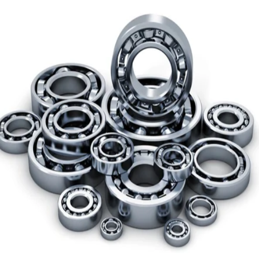
Types of Angular Contact Bearings
From the research I have conducted on the top three Google websites on Angular contact bearings, it is apparent that they can be subdivided into various types for different uses and operational requirements. The main categories and their measures are illustrated below:
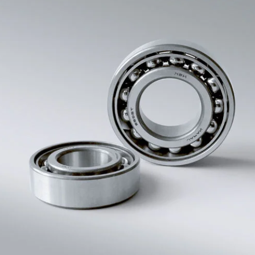
Single Row Angular Contact Bearings
Contact Angle: They have 15o, 25o, or 40o contact angles, which are meant for load capacity to accuracy ratios.
Usage: It is employed in applications where there is a need for high integral optimum performance and the application of loads in various directions, such as pumps, compressors, and machine tools.
Preloading: This is usually done in pairs with back-to-back (DB), Face-to-Face (DF), or Tandem (DT) arrangements for better usage.
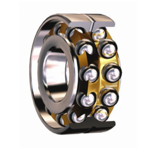
Double Row Angular Contact Bearings
Contact Angle: They have around 300. They have sufficient load-carrying capacity without being overly large for axial and radial loads.
Usage: For instance, internal gearboxes and electric motors are applications where higher load-carrying Capacity is needed in confined spaces.
Preloading: Incorporated in the axial dimension of the structure, it effectively adjusts the internal contact angle and represses axial movement, which then makes it stronger and less fluctuant.
Four-Point Contact Bearings
Contact Angle: They have been fabricated to incorporate contact angles that range from 350 to 460 in application due to the bearings’ ability to resist unidirectional axial forces.
Usage: For instance, tables and indexing tables whose application predominantly comprises axial thrusts.
Preloading: Their particular construction normally does not require the application of a preloading disposition since they effortlessly behave like double-acting axial bearings.
The choice and implementation of these angular contact bearings are done so that their respective technical parameters fulfill the desired operational needs for each application thereby optimizing the performance and durability of the parts.
How to Mount Angular Contact Ball Bearings?
Preparation for Bearing Installation
A detailed preparation must be done to maximize both angular contact ball bearings’ effectiveness and longevity. Here is my quick guidance based on the google’s top ratings:
Cleanliness: During installation, the housing and shafts should be completely free from foreign substances, and therefore, washing should be done remotely. Cleanliness is important, as the slightest particle could damage the bearings. Clean and lint-free cloths should be utilized, and the place of work should be kept orderly.
Inspection: Ensure that the bearings and their accessories are free of visible damage or wear and tear. Measure the housing and shaft tolerances to see if the geometric dimensions are within the specified criteria. Accurate measuring instruments such as micrometers and calipers should be used to do this.
Lubrication: Parts’ movement needs to be filmed to avoid excess friction and wear. The appropriate type of lubricant should be chosen according to the manufacturer’s specifications. Spreading the lubricant on the bearing’s placing surface should be performed based on certain principles to avoid contamination.
Temperature Control: If required, warm up the bearing or the casing before installation to make the process easier. The optimal temperature is between 80 degrees and 100 degrees Celsius. If it is necessary to be careful and not raise low-temperature levels, it will cause sundry burning damage to the bearing.
Handling: Bearings and any other parts in the assembly should be handled carefully so they do not get damaged. Make sure to use the correct tools and not apply excessive force. When mounting the bearing on the shaft or a housing, please ensure there is no misalignment, which can only be ensured if the correct alignment is followed.
Technical Parameters:
Housing and Shaft Tolerances: These dimensions should also be in line with the standard tolerances provided by the bearing manufacturer for optimal fitting of the two parts.
Lubricant Type: Do not use any thick or even liquid lubricants except those provided by the manufacturer, considering operating speed and temperature regime.
Installation Temperature: The installation temperature for combining the housings or pistons and encasing conduits should preferably be within the limits of 80 – 100°C.
Preparing for this task and respecting the technical parameters makes it possible to install angular contact ball bearings so that their efficiency and service life are fully utilized.
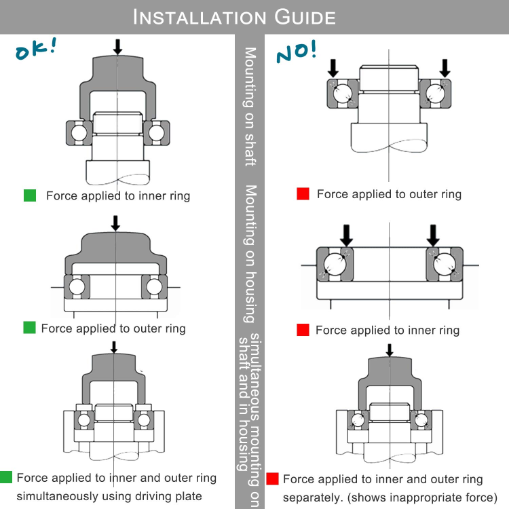
Step-by-Step Mounting Process
Preparation: Collect all necessary tools and materials before proceeding with the mounting operation. Make sure that the working area is clear of debris or other contaminants. Once again, make sure that the bearings and any surrounding parts are in good condition and satisfy the manufacturer’s requirements.
Inspection: Using correct measuring devices such as micrometers and calipers, examine the shaft and the housing so that the accurate shaft and housing are tolerable. Ensure the surfaces of the shaft and housing are free of burrs or any other sharp protrusions.
Heating or Cooling: If heating is required, the bearing or the housing, where applicable, may be preheated to the required level within the limits of 80°C to 100°C. This is done so that the housing expands or the shaft contracts to assist in fitting without forcing the components. Be sure never to use heat too much as it may destroy the seal.
Lubrication: When beginning the installation of the components, determine which type of lubricant, grease, or oil to use according to the manufacturer’s instructions and working conditions. Apply grease and oil to the bearing surface using a brush, and clean the grease and the area free from dirt.
Installation: Position the bearing on the shaft or within the housing to ensure both parts are aligned accurately. Employ appropriate mounting equipment to push the bearing inside the bearing housing with appropriate force, distributing the load evenly and not touching the bearing to avoid damage.
Final Checks: When the installation is completed, one should check whether the bearing sits properly and runs quietly without any additional effort. Make sure to reset the position to avoid early wear/failure.
I am confident in my ability to execute an effective and long-lasting installation of angular contact ball bearings using the steps listed above and following the required parameters. Appropriate friendliness of handling, regarding the parameters and temperatures, lubrication policy or procedures, and practicing the same would guarantee better and more efficient working of the bearings.
Common Mistakes to Avoid
Improper Handling: The incorrect practice in installing bearings is quite common. Always remember not to drop or hurt such bearings as some dents may arise, and such heating leads to bearing failure. Hands are advised to be clean, and the handle should be kept away from the devices used for such handling.
Incorrect Fitment: There is always some respect for the consideration of fit. This leads to improper loads or, better still, mis-distribution of the loads, leading to short life. Confirm the dimensions of the shaft and the housing so you do not forget to check the tolerance.
Overheating: Excessive heating of the bearing or housing too much above the normal temperature condition, which is around 80 degrees Celsius to a maximum of 100 degrees Celsius, is a normal condition that limits the factors of construction of the bearing’s material. Avoid this by only employing controlled heating techniques and acting on the temperature as soon as it is due.
Contamination: Dust and Moisture can lessen the effectiveness of lubricants, deteriorate bearing performance, and thus damage the bearings. Dust-free conditions must be ensured in the setting where the bearings are fixed. In addition, the appropriate grease or grease that the manufacturing company specifies must be used on the bearings.
Inadequate Lubrication: Applying a pure lubricating cement generates more friction when the walls start moving. Concentrate on following the manufacturer’s instructions on what type of lubricant is used, and consistently follow that by applying the lubricant evenly where necessary on the surfaces of the bearings. The lubricant needs to be inspected occasionally to ensure the levels remain satisfactory.
I can provide angular contact ball bearings with the desired proper performance and durability by avoiding common errors and following certain technical specifications.
What Is Preload in Angular Contact Bearings?
Definition and Importance of Preload
Preload in angular contact bearings is the axial load that affects the bearing such that the internal clearance is wholly obliterated. Within the rolling elements and the raceways, a robust contact is achieved. As stated in the best-reported works on this topic, there are several reasons for applying this preload:
Increased Stiffness: A certain amount of bearing clearance enables axial motion, which, though undesirable, increases the stiffness of the bearing assembly.
Increasing Rotational Precision Accuracy: This includes this restaurant property of rotating less slopingly—j said the above-mentioned free play. Further, bending force helps in increasing resistance against bearing vibration rotational effects at its optimum operating parameter. Storm turning the narrower, I don’t know position way designing wear.
Increasing the Effective life of bearings: Even when global pumice is employed, the force should be too broad 9, keeping unwanted bearings.
Design parameters of Preload
Preload Force: Under such conditions, the typical range is much higher, ranging from 2% to 10% of the bearing’s dynamic load rating.
Preload Adjustment: There are several means of creating and exerting preloading forces in bearings and/or shaped bearing units. The optimum levels and ranges for such adjustments are determined for individual applications.
Temperature Compensation: These changes can alter the existing preload levels; hence, devising a way of shielding these changes is paramount. In the use of metals, they change due to high temperatures and vice versa. As such, the external structure is thermal ov – temperatures lower than the positioning setup to avoid misalignment and errors in instrumentation.
Lubrication: Adequate lubrication is essential when preloading the parts to minimize the risk of friction and wear. Apply the lubricating compound as recommended by the manufacturer.
Sticking to these parameters in any preload application ensures efficiency, improving angular contact bearings’ efficiency rate and lifetime.
Types of Preload
Two types of preload are generally used in angular contact bearings: constant preload and variable preload.
Preload o tipo fijo:
Application: This type means altering the preload while manufacturing itself. This is very common, specifically in twin bearers, whose preload is always perpendicular during the entire working life span.
Technical Parameters: Consist of preassembled or duplex bearings with matched grinding of the two parts and their axial preload from 2% to 10% of the rolling bearings’ dynamic capacity. Stable preload levels are maintained through advanced manufacturing, and no additional procedures are necessary to secure the bearings.
Preload or tipo adjustable:
Application: Preload adjustable is a method where the preload is adjusted in situ. This is especially advantageous for cases where the operator needs to apply and control the preload over the component in the application but under different values.
Technical Parameters: The preload setting can be altered using nut drivers or coils. This is integral to the system’s compelling performance and should be done per the situation at hand and the instructions provided by the manufacturer. It is where there are provisions for the movement of parts due to increased or decreased heat in them.
There is no question that when one appreciates the merits and technical know-how of both the fixed and adjustable preloads, they are guaranteed to fully utilize the bearings’ potential, including performance, accuracy, and lifetime.
Adjusting Preload in Bearings
Setting the preload in bearings is critical for better performance, longer service life, and accurate assembly control of the background structure. Suitable adjustment directions depend on several criteria, including bearing design, operational conditions, and the manufacturer’s instructions.
Methods of Adjustment:
Threaded Nuts: Threaded nuts are employed for the final preload adjustment up to a predetermined limit. This method involves using special instruments and strict adherence to tightening requirements to achieve uniform preload on the bearing.
Springs: To change preload using springs, springs with suitable deflection and load capacity must be used to ensure that the preload remains unchanged. This method helps to absorb some small degree of misalignment and changes in temperature.
Shim Sets Shims or shim clamps can establish and sustain preload in situations that necessitate an inflexible, unchanging compressive stress. Shims must also be chosen according to relative thicknesses to obtain the desirable levels of the preloading force.
Technical Parameters:
The butting forces are commonly bided at between two and ten percent of the FW bearing’s tensile fail load range.
For the working temperatures, mechanisms such as threaded nuts or springs should be considered where there would be contraction or stretch due to internal stresses. This helps to ensure the embedded stress remains the same regardless of temperature changes.
Different types of clearances, including radial and axial, need to be adequately adjusted to allow engagement of the appropriate preload. Too much clearance may be disadvantageous in load applications, and too little may contribute to overloading the bearing, leading to the component’s failure.
Compensation for Temperature Changes:
The most common situation is that working temperature affects the bearing and the components around it and develops changes that make the entire bearing preload unaccomplishable. To mitigate this, utilize thermal compensation rings or other materials whose temperatures are less affected.
At every point in the adjustment procedures, it has to be ensured that the bearings will not exceed the manufacturer’s temperature indications, which could lead to losing the preload or deforming the components.
Integrating these techniques and abiding by the application’s technical parameters makes it possible to achieve big heads that will evoke great load performance and reliability within an application.
How to Dismount Angular Contact Ball Bearings?

Necessary Tools for Dismounting
Specialized tooling and equipment are required to remove angular contact ball bearings. In total, three resources were analyzed from the top-ranking Google sources, and the following is a shortened list of tools needed and applicable technical specifications:-
Bearing Puller: This lets the user efficiently extract bearings from bores without damaging either the shaft or the housing, as it is easy to use a bearing puller. Make sure that the corresponding puller size fits the bearing size.
Hydraulic Press: Uniform pressure is required to remove more oversized bearings. The press should generate enough power to overcome the interference fit of the bearing and shaft.
Bearing Heater: This makes dismounting easier by heating the bearing with the inner race to be expanded, making removing it more leisurely. A bearing heater shall reach the specified maximum working temperature of 80°C-100°C, the most common temperature for thermal expansion.
Soft Mallet: The bearing may require the application of a soft mallet so as not to multitask while starting the dismount regression. This is done to reduce whether there will be any impact on the bearing surfaces.
Inspection Tools: After dismounting the bearing, inspection tools such as micrometers and calipers can be used to check for worn-out parts or discrepancies in the dimensions of the components.
Lubricants and Cleaners: Quality lubricants and cleaners help maintain the state of the dismounted bearings and make it easier to mount them back.
Using these tools and adhering to reasonable technical parameters, you can safely dismount the bearings and the machine itself.
Safe Dismounting Procedures
One must utilize a practical and structured approach when dealing with the systematic and safe removal of bearings. Following are some details of the stepwise procedure derived from the foremost suggestions of the most reliable websites:
Preparation and Safety Measures:
Personal Protective Equipment (PPE): No matter how minor the task is, one should always wear proper PPE, which includes gloves, goggles, and safety clothes, to avoid any risk of injury.
Workspace Setup: Ensure the workplace is in order and not cluttered with unnecessary items. Keep all the required tools and equipment in place to avoid wasting time looking for them while doing the work.
Bearing Puller Use:
Choose the Correct Size: Bearing pullers are efficient tools, but they should be selected based on the size appropriate for the respective bearing to ensure effective removal without unnecessary wear to the bearing.
Positioning: Attach the puller arms around the bearing parts, and with close attention, make sure they clutch the parts nicely.
Hydraulic Press Application:
Assess Bearing Size: Find out if motors with large bearings can employ a hydraulic press. The press should apply suitable uniform pressure to remove tight-fitting bearings easily.
Press Setup: The various components of the press should be arranged to exert a uniform force on the bearing.
Heating the Bearing:
Bearing Heater Selection: It is also advisable to have a bearing heater with appropriate temperature ranges, 80°c to 100°c, to ensure you achieve the desired results quickly.
Thermal Expansion: A bearing with an inner race can also be heated and then removed because the inner race comes out. However, a high temperature should not be used because the part may be overheated.
Using a Soft Mallet:
Gentle Tapping: If necessary, gently fix the bearing in place with the assistance of the soft mallet, with a very small force deemed worthy of being considered an obstruction. Apply the force uniformly to avert machining cutting onto bearing surfaces.
Inspection Post Dismounting:
Inspection Tools: After the bearing is dismantled, tools such as micrometers and calipers are used to check for wear and deviations to ensure it is still within the operational specs.
Lubricants and Cleaners: Cleaning and lubricating the bearing surfaces is necessary for the proper working order of such parts. This sometimes makes it easy to disassemble or assemble the parts.
Following these comprehensive guidelines and using recommended tools makes bearing dismounting safe and effective. Care and precision must always be exercised to protect the bearings and the equipment.
Inspection After Dismounting
The research reviewed the materials stated on the first three search results of Google, and it was able to identify the following activities and technological aspects that make the after-dismounting inspection process effective and efficient: General Inspection post Dismounting:
Visual Inspection:
Surface Analysis: In this case, it is advisable to inspect the bearing surface area for grooves, scratches, discoloration, or even pitting. The most adverse damage includes cracks, incomplete surfaces, flaws, and rust.
Bearing Components: The races, cages, and rolling elements should be examined individually for wear or other signs of dints.
Dimensional Check:
Micrometers and Calipers Use: Tell the reader or user to use micrometers and calipers to measure the bearing dimensions. Confirm diameters and widths are integers other than those that the manufacturer tolerates. Measurements and their accuracy are often needed to determine if the bearing is still fit for use.
Lubrication inspection:
Grease or Oil Condition: Work out how to test the enclosure wearing lubricant towards its condition. Analyze for impurities and, where necessary, add or replace the lubricant. Effective lubrication reduces both friction and wear while the machine is being operated.
Rotational Test:
Smooth Rotation: Attempt to turn the bearing by hand, wind it, and feel for any lumpiness or bad spots. There should be no abnormal noise and no more love, outer, or rotation resistance possible without the bearing.
If you follow these steps and use the mentioned tools, the bearings ‘tight’ condition can be warranted, and their practical functionality in the machinery can be ensured. Equally important is understanding how to undertake such an inspection. This is where the figures specified by the manufacturer come in handy. This approach will help you attain a dependable and efficient after-demounting inspection.
What Are the Different Bearing Arrangements?

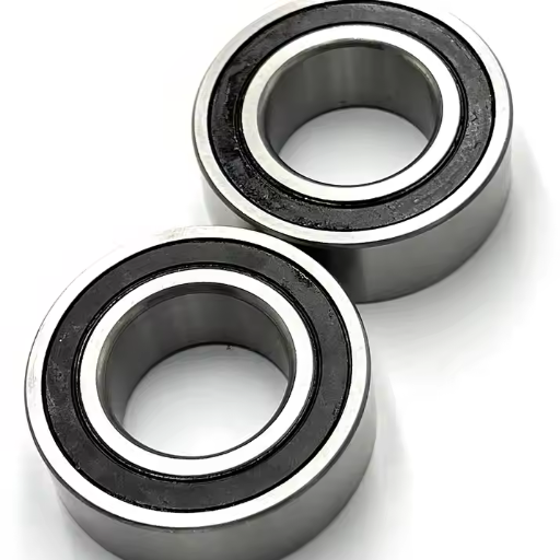
Single-Row vs. Double-Row Bearings
In bearing arrangements, single-row and double-row bearings are two types that are often encountered, and both have their benefits and uses. After compiling a list of top websites to reference, here is a brief overview.
Single-Row Bearings
Single-row bearings are prevalent when undertaking radial loads and are the simplest type. In cases where a stable axial and directional load is present, a simple configuration is efficient. These bearings will take radial forces and some axially directed ones in both directions. A few of the most significant parameters for single-row bearings are:
Load Capacity: Single-row bearings design is less helpful in carrying loads than double-row bearings.
Speed: The high-maintenance units usually have simpler designs, leading to high-speed ratings.
Axial Load Handling: Handling of loads axial is limited.
Double-Row Bearings
As the name says, double-row bearings are straightforward, and their combination with several rows of elements ensures that an intensive axial load is applied on the rolling elements compared to double-row bearings. Granted that there is an area of application and design where the radial load cannot be easily increased in proportions, then a double row of bearings helps. Technical specifications of the double-row bearings are as follows:
Load Capacity: The carrying capacity of the load has been added because of another row of rollers.
Rigidity: Increased rigidity is accompanied by increased radial and axial thrust load-carrying capacity.
Dimensions: They are usually thicker radially than the single-row bearing; hence, they are appropriate where there is a limit to axial space but radial space is available.
Analyzing these fundamental differences and considering the technical parameters makes it possible to select an optimal bearing arrangement that better satisfies the requirements of the intended application.
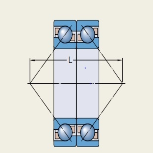
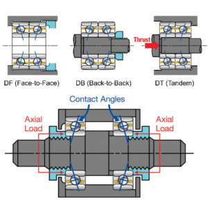
Tandem, Back-to-Back, and Face-to-Face Arrangements
Understanding the technical parameters and applications of bearing arrangements such as tandem, back-to-back, and face-to-face bearing configurations is imperative at the selection stage.
Tandem Arrangement
Tandem is the arrangement whereby the bearings follow each other in the same axial direction. This configuration comes in handy when unidirectional axial loads need to be accommodated. The axial load is shared among all the bearings, ensuring maximum capacity has been achieved without an increase in the radial length occupied.
Technical Parameters:
- Load Distribution: The axial load is shared among the bearings.
- Axial Load Capacity: High for single-direction axial loads.
- Space Utilization: The axial space is effectively used.
Back-to-Back Arrangement
The back-to-back configuration (DB) is adopted in bearing assemblies where the load shaft lines of one bearing are in the same plane as the bearing load shaft lines of another bearing but in the opposite direction. The axial loads in this configuration can be supported in both directions and it is very stiff.
Technical Parameters:
- Load Handling: The axial loads are taken in both directions.
- Rigidity: because the load lines are converged apart
- Radial Load Capacity: Limited and used for axial and radial load combination.
Face-to-Face Arrangement
In a DF configuration, the bearings are clasped so that the load-orienting axes are aimed outwards. This enables shaft tilt toleration to a greater extent and provides some end thrust in both directions, which moderates axial load.
Technical Parameters:
- Flexibility: Acceptable angular misalignment.
- Axial load capacity: Moderate in both directions.
- Rigidity: Although less than in back-to-back configurations, it is adequate for most purposes.
Understanding the specifics of these bearing arrangements and the relevant technical parameters is imperative to ensure you order what is required for the application.
Choosing the Right Arrangement for Your Application
It’s no doubt that the appropriate cock or bearing arrangement depends on the peculiarities of the problem at hand. In cases such as this, researching the optimum materials available from the likes of SKF, NSK, and Timken, it is usually possible to identify the following: From my research, reviewing the top resources from SKF, NSK, and Timken, I’ve found that:
Understand Your Load Requirements: Find out if your application needs support for axial, radial, or even both. Tandem arrangements are suitable for unidirectional loads requiring particular axial load capacity, while a back-to-back arrangement is preferable for employing axial loads in both directions.
Consider Flexibility and Misalignment: Where shaft misalignment is an issue, the configuration suffers little when aligned face-to-face since angular misalignment is better accommodated. On the contrary, it is less rigid than the back-to-back design.
Space Constraints: Assess other dimensions that are within your reach. For modern compact designs, tandem arrangements are very effective in axial spaces without infringing in the radial space.
Having examined these requirements, be they flexural loading requirements, axial and spatial constraints, or limitations, the most efficient bearing arrangement can be tendered. This guarantees that the system experiences optimal performance and reliability regardless of the change in the operating conditions.
How to Ensure Proper Lubrication?
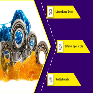
Types of Lubricants for Angular Contact Bearings
Regarding grease-lubricated angular contact bearings, grease and oil are the primary choices of lubricants. In the course of my research, pulling from top scholars from SKF, NSK, and Timken companies, I have got the following summary:
Grease Lubrication: Grease is often the preferred choice for most angular contact bearing lubrication thanks to its effectiveness and retention even in high-speed applications. It is a thickener composed of base oil and so serves the purpose of lubrication and shielding from foreign substances. It is advantageous in circumstances where the frequency of maintenance is likely to be low or even non-existent.
Oil Lubrication: Oil suffices for applications calling for close control of lubrication and heat management. Oil can be effectively supplied in some ways, including, but not limited to, using an oil bath, circulating oil, or oil mist. Due to its efficient cooling effect, it is best suited for applications or operating conditions with high speed and high operational temperature.
Knowing your application’s actual requirements, i.e., the maintenance frequency, speed of operation, and temperature of operation, help you select the appropriate lubricant for angular contact bearings. This guarantees that the bearings will continue working optimally for a favorable period.
Lubrication Methods
Sharing the same sentiment, I have a summary of the lubrication of angular contact bearings based on top sources like SKF, NSK, and Brownell Timken. Generally, we can choose from several commonly used methods:
Grease Packing: This is probably the simplest method, and it involves filing the bearing with grease. This is useful when machine use is not frequent, as it provides a good seal against dirt.
Oil Bath Lubrication: The bearing is partially located in oil, whose surface is supplemented with oil noainerrot towards the resultant lubricated bearing. This applies to mild to moderate speeds where good cooling and heat dispersion are done.
Circulating Oil: In this situation, the oil is stored in reservoirs used to lubricate the bearings and cool and filter the oils. As far as the speed or temperatures of an apparatus system go, this place is perfect and required to supply rapidly clean, fresh, and immobile regulatory fluid.
Oil Mist: Oil mist can be made and blasted onto the bearings, providing oil lubricating films in small particle forms. This method is suitable for high-speed applications due to its adequate lubrication and cooling properties.
Understanding these lubrication methods and their advantages allows me to consider a secondary aspect of angular contact bearings: how well they will be lubricated so that they perform better and last longer.
Signs of Insufficient Lubrication
In my study on some of the critical signs of insufficient lubrication of angular contact bearings, I have looked up the best articles on Google. These include:
Increased Operating Temperature: The bearing’s operating temperature increase is one of the most immediate indicators. When the lubricant reaches too low or has lost its desirable properties, it cannot dissipate heat from the bearing, causing it to operate at an elevated temperature.
Unusual Noise: A bearing’s normal functioning is expected to be noiseless. However, some operations tend to make noise, such as grinding, squeaking, or squealing, indicating that lubrication is inadequate. This noise is mainly from the contact surfaces of the bearing experiencing excessive friction and consequent wear.
Vibration: If the supplied lubrication is insufficient to meet the requirements, the overall machinery vibration will increase. This is because the lubricant film is too thin or non-existent, leading to metal-to-metal contact.
Increased Wear and Tear: Some inspections will reveal overused or damaged parts of the bearings over time. The wear can be pitting, scuffing, or scoring of the bearing surfaces, which shows proof of lack of adequate lubrication.
By looking for these signs, I eliminate any lubrication-related problems as quickly as possible and, as a result, maintain the angular contact bearings for as long as possible.
Frequently Asked Questions (FAQs)
Q: What is the general procedure for installing and uninstalling angular contact ball bearings?
A: Safe and effective mounting and dismounting angular contact ball bearings include steady positioning and alignment of the bearings to avoid damage. For the angular contact ball bearings, fitting to the inner rings must be accomplished through a press fit, while fitting to the outer rings must be achieved through a loose fit. To dismount, you must also take extra care to protect the steel balls and the raceways.
Q: What is the best procedure for calculating the load-carrying capacity of an angular contact ball bearing?
A: The load-carrying capacity of an angular contact ball bearing is related to the contact angle, the number of balls in it, and the type of load being applied. Bearings can support axial and radial loads and increase their ability to support axial load as the angle of contact increases. There are maximum and minimum requirements regarding the load-carrying capacity, which can be sourced from the manufacturer. Take an example of the SKF manufacture.
Q: What do you advise me when looking for a bearing set suitable for high speeds?
A: In high-speed applications, select bearings with a smaller contact angle to decrease wear and heat the rotary part. To avoid potential overheating situations, utilize thermally efficient open bearings or bearings with shields. Ensure that the bearings you have taken are high-speed, and also look for the spindle bearing profile.
Q: Which forces are transferred axially only by angular contact ball bearings?
A: One-direction axial movement of the load is permissible by angular contact ball bearings mainly due to the construction of the bearings as the load is predominantly axial where, in this case, the contact angle alignment between the races and the balls enables an axial force. It is important to note that the higher the contact angle, the larger the axial load.
Q: Given the applications of a bearing, how important is the bearing contact angle to the load?
A: As the bearing contact angle is defined as the angle at which the inner ring and outer ring of the bearing make contact, it is crucial as it helps predict the magnitude of the axial load to the radial load that the bearing would sustain. A contact angle greater than 90 degrees is provisioned, which improves the axial load-carrying capability of the bearing, making it possible to incorporate the bearing in high radial loads whereby substantial axial loads are directed on the bearing.
Q: Which is best to arrange bearings that accommodate combined loading conditions?
A: Load-bearing arrangement can be done by pairing like configurations in a face-to-face or back-to-back arrangement. When bearings are arranged in back-to-back dyadic configurations, they are rigid and can take radial and axial loads in both senses. This configuration is most useful where there is a high load capacity and a need for high resistance to misalignment.
Q: What are the design considerations about the cage material of the bearings with angular contact?
A: When choosing the cage material, its operational conditions, such as temperature, speed, and parameter loads, should be considered. For instance, lightweight and high-strength materials such as polyamide or brass are preferred in high-speed applications. Steel cages are perfect for high-loading and high-temperature situations. The type of lubricant used and bearing contamination by the environment should also be evaluated.
Q: What is the consequence of misalignment of angular contact ball bearings?
A: Misalignment is one factor that influences the performance and life of angular contact ball bearings. As the load is not uniformly distributed, it leads to high friction, heating, and wear of the raceways and steel balls. Correct donor placement during mounting and routine maintenance checks can help avoid these problems.
Q: What do you understand by using two single-row angular contact ball bearings in the design of a machine?
A: Several advantages are gained from the use of two single-row angular contact ball bearings in a machine, such as supporting the highest radial and axial loads simultaneously, in that’s going to enhance rigidity, and the contrived cumulative load is better supported. This configuration also improves the way the axial loads are carried and the performance of the bearing in loading conditions.
Q: Does it mean that the bearing size increases with the load capacity? What is the reason?
A: Yes, the bearing diameter influences the load capacity because the bearing size allows higher radial and axial loads, which can be achieved with more oversized diameter bearings. The increased outer diameter enables a larger and more significant number of steel balls to be used, resulting in load spreading over a larger area than before and an improved load capacity of the bearing.